Shaker - PowerPoint PPT Presentation
1 / 2
Title:
Shaker
Description:
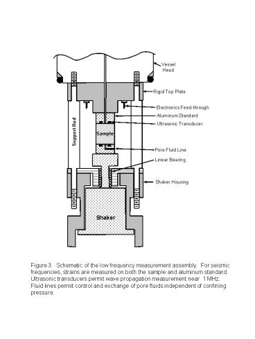
For seismic frequencies, strains are measured on both the sample and aluminum standard. ... 13. Bond foil gages to. central kapton strip. 11. Remove protective tape ... – PowerPoint PPT presentation
Number of Views:64
Avg rating:3.0/5.0
Title: Shaker
1
Vessel Head
Rigid Top Plate
Electronics Feed-through
Aluminum Standard
Ultrasonic Transducer
Support Rod
Sample
Pore Fluid Line
Linear Bearing
Shaker Housing
Shaker
Figure 3. Schematic of the low frequency
measurement assembly. For seismic frequencies,
strains are measured on both the sample and
aluminum standard. Ultrasonic transducers permit
wave propagation measurement near 1 MHz. Fluid
lines permit control and exchange of pore fluids
independent of confining pressure.
2
1. Ends flat and parallel (length should 2.5
to 3 times diameter)
5. Cut strip of Kapton (polyamide) film (
), protect outside surface With removable
tape ( )
2. Coat sides with stiff, waterproof epoxy
let set, then smooth off rough points
3. CT scan
6. Epoxy on center strip of Kapton (polyamide)
film
3 cm
7. Set in place and apply slight pressure with
thin teflon thread tape ( )
4. Protect ends with tape ( )
- 8. Attach aluminum end pieces
- (remember to align P- and S- transducers)
- - Allow bond to cure
- Test transducer signals
- Clean out pore fluid holes
10. Add end sheets of kapton, overlap center
kapton and aluminum.
9. Protect about 2.5 cm of center kapton surface
with removable tape. Protect ends of aluminum
with tape
12. Bond semiconductor gages to aluminum
wire
11. Remove protective tape
13. Bond foil gages to central kapton strip
15. Cast on outer Jacket of flexible epoxy
14. Strip about 2mm of protective enamel off ends
of coated magnet wire. Attach wire to gages.
Bring wires out to top, sick in place with 5
minute epoxy


