NanoTest indentation module - PowerPoint PPT Presentation
1 / 13
Title:
NanoTest indentation module
Description:
Elastic and plastic work. Elastic recovery parameter. E/H ratio. Stress-strain ... and Nano-tribology results. Follow-up project dynamic loading and fatigue. 9 ... – PowerPoint PPT presentation
Number of Views:260
Avg rating:3.0/5.0
Title: NanoTest indentation module
1
Indentation
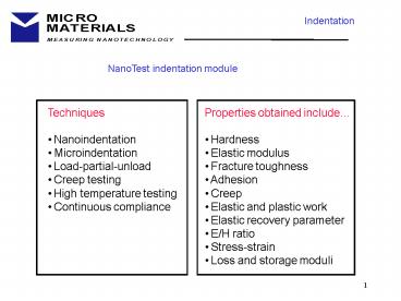
NanoTest indentation module
- Techniques
- Nanoindentation
- Microindentation
- Load-partial-unload
- Creep testing
- High temperature testing
- Continuous compliance
- Properties obtained include
- Hardness
- Elastic modulus
- Fracture toughness
- Adhesion
- Creep
- Elastic and plastic work
- Elastic recovery parameter
- E/H ratio
- Stress-strain
- Loss and storage moduli
2
Indentation Data Analysis
Fused silica is isotropic - hardness and
modulus are constant with depth
8 indentations 120-200 mN
3
Indentation Case study
Quantitative measurement of the mechanical
properties of thin films
Comparison of load ranges
Technique Applied Force SPM nN-mN NanoTest 10
mN-500 mN MicroTest 100 mN - 20 N Hardness N-kN
Aim determine the hardness and modulus of top
layer in IC bond pad without substrate influence
4
Trial indentation too deep! - max. depth is
gt0.5 top layer thickness
fracture
5
Indentation Case study
Depth-profiling of mechanical property variation
Load-partial-unload technique
1 quick-and-easy experiment at a single
point 20-cycle load-partial-unload Depth
controlled 50-1000 nm Experiment time 30
min Analysis time 30 sec Comes as standard with
basic Indentation module
- produces rapid and quantified variation in
hardness and modulus with depth
6
Indentation Case study
Hardness of 5 mm Ni-based top-layer of bond pad
coating substrate
coating
coating substrate
decreasing hardness
constant hardness
- 1/10 rule - for a hard coating on softer
substrate - - this works for hardness only - 3-5 better
estimate for modulus
7
Depth profiling with the load-partial-unload
technique
Plasma-polymers deposited at 100 W and 25 W power
100 W
25 W
25 W
100 W
20 cycle load-partial-unload experiment takes
30 mins
8
Use of Nanoindentation to assess new candidate
surface modification technologies for biomedical
applications
Data from European project Ion Beam Surface
Modification of Polymers for Improved Friction
and Wear Properties Micro Materials Ltd
(UK) University of Birmingham (UK) Technical
University of Clausthal (Germany)) SC Plasmaterm
(Romania) Hungarian Academy of Sciences (Hungary)
Wear resistance predicted from H/E ratio
correlates to Pin-on-Disk wear tests and
Nano-tribology results Follow-up project
dynamic loading and fatigue
9
Indentation mapping (1)
How homogeneous is my coating? An example of
nanoindentation as a QA tool
- rapid, automatic scheduling
- of arrays of indentations - 10,000 points
- per single run - or 100 scratches
10
Indentation mapping (2)
Mapping variations in hardness and elasticity at
the nanoscale
Precise indent placement with a 4-objective high
resolution metallurgical microscope NOTE 1
objective can be replaced by contact/AC mode SPM
10 repeat indentations to 50 nm depth along 10 mm
alloy interface between stainless steel surfaces
show clear phase separation
- studies of nano- and micro- scale phase
separation
11
Indentation mapping (3)
Mapping the hardness of tribological coatings
H(GPa)
Softer phase to provide toughness
Harder phase to provide abrasive resistance
5.2 micron Ion-beam Assisted Deposition (IBAD)
Alumina Stephen Abela, Unversity of Malta
12
Mapping hardness and modulus
Nanomechanical properties of burnt polyurethane
foams in resin
Modulus (GPa) Hardness (MPa)
optical image
Nano-mechanical properties of heterogeneous,
multi-phase soft samples can be quantitatively
mapped
13
Bringing nanomechanical measurements into the
real-world
Nanomechanical testing at high temperatures
Horizontal loading configuration has advantages
for drift-free high temperature tests
Environmental Control critical for accurate
measurements (1) on viscoelastic materials (2)
at high temp
The NanoTest high temperature stage
- Hot stage specifications
- Indentation to 750 degrees Celsius
- Scratch testing to 750 degrees Celsius
- Thermal drift minimal
14
High temperature nanoindentation
- Minimal thermal drift during indentation at high
temperature
- Thermal drift very low due to-
- hot stage design
- horizontal configuration
- environmental control
- thermalisation time
High temperature nanoindentation testing of
fused silica and other materials BD Beake and JF
Smith 2nd International Indentation
Workshop Cambridge University July 2001 Phil Mag
A vol. 82, pp 2179-2186, 2002
Indentation into FS at 400 deg. C 60 s hold at
90 unloading - no thermal drift is seen
15
Influence of test temperature on nanoindentation
of thermal barrier coating
Nanoindentation of EB-PVD TBC (Zirconia/8wt
yttria) 25, 500 and 750 degrees C
3 curves at 750 deg. C
- Heterogeneous columnar coating complex
indentation response even at RT - Probability distribution functions can be used to
determine results affected by porosity and
natural scatter - Sapphire indenter mounted in Mo stub was used
for 750 degree indentations - Clear fracturing during loading
- Minimal drift at 90 unloading
Fracturing during loading
J.R. Nicholls, S.A. Impey, R.G. Wellman, A.G.
Dyer (all Cranfield University) and J.F. Smith
(Micro Materials), ICMCTF 2003
16
Influence of test temperature on nanoindentation
of thermal barrier coating
- Hardness and modulus decrease with temperature
Hardness Room Temp. 5.84 ? 1.04 GPa 500
C 4.15 ? 0.74 GPa 750 C 2.89 ? 0.49 GPa
Reduced Modulus Room Temp. 157.12 ? 12.78
GPa 500 C 123.24 ? 14.74 GPa 750 C 102.16
? 15.05 GPa
17
Dynamic nanoindentation Continuous compliance
Dynamic nanoindentation analysis Find contact
damping and contact stiffness with ? atan(a
a0x)?/(k1k2x - b?2 c where ? measured
phase at depth x a0 contact damping k2
contact stiffness, respectively a, b and c are
constants (det. by cal.) k1 pendulum spring
stiffness (8 N/m) ? angular frequency (40?
rad/s)
Highly cross-linked resin Time constant
1s Frequency 20 Hz Indentation depth 1-1.8 micron


