The Design of Helical Magnet - PowerPoint PPT Presentation
1 / 16
Title:
The Design of Helical Magnet
Description:
This field map shows the magnetic field over 5 gauss at radius = 30 inches. ... This graph shows the difference of the magnetic field between the Measured and Perfect ... – PowerPoint PPT presentation
Number of Views:53
Avg rating:3.0/5.0
Title: The Design of Helical Magnet
1
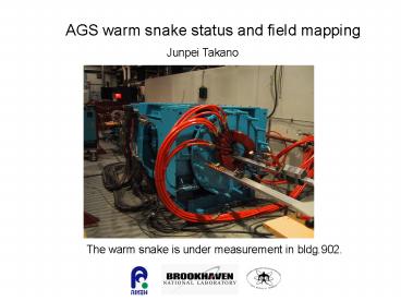
AGS warm snake status and field mapping
Junpei Takano
The warm snake is under measurement in bldg.902.
2
Temperature rise
37 ?
20 ?
Thermo graphic data _at_ 2700Amp.
3
Temperature rise at full current
Average temperature rise 10.5 ? _at_ total water
flow rate 185 gal/min
Calculated data temperature rise 14.8 ? _at_
total water flow rate 162 gal/min
4
Magnetic field around the warm snake
This field map shows the magnetic field over 5
gauss at radius 30 inches. Under 5 gauss is the
security area for persons who has the pace maker.
5
Magnetic field around the warm snake
80 inches
70 inches
This field map shows the magnetic field over 5
gauss at z 50 inches.
6
Magnetic field on the z-axis
7
Simulated beam trajectory
L1 39 cm, L2 132 cm P1 90
cm/rev , P2 184 cm/rev
these parameters were optimized
L2, P2
L1, P1
L1, P1
offset 0
offset 0
deflection angle 0
This beam trajectory is perfect !
8
Beam trajectory
depending on the energy
9
Error study
However these beam trajectories are the result of
the ideal simulated model. The actual magnet has
some errors. The main errors which should be
considered are B-H curve of the steel Packing
factor of the laminations Coil position
error Dimensional errors of the yoke and
laminations because of the lamination
pressing. ? The model which is completely like
the actual magnet must be simulated.
10
Measured magnetic field
This graph shows the difference of the magnetic
field between the Measured and Perfect which is
caused by the saturation of the steel in rapid
pitch region.
11
Measured magnetic field
This graph shows the Field Angle.
The coil has its outlets on this side.
12
Beam trajectory
offset and deflection angle
This is the beam trajectory of the actual
model. The output beam has offset and deflection
angle. Magnetic flux at the center of the magnet
is 1.53 Tesla.
13
Beam trajectory
depending on the current
Current 80 to 110
The operation current is one of the method for
correcting the beam trajectory.
14
Beam trajectory
The Beam output position will be varied on this
way, if the shims are put on the pole piece.
15
The result of the matrix about the current and
shims are current 94.5 shims
x0.7 This trajectory is the output with 95
current and a shim.
Beam trajectory
Magnetic flux at the center of the magnet is 1.46
Tesla.
16
Summary
The measured data being compared to the simulated
data. We know the way to correct the beam
trajectory with shims and operating current.
Measurement plan
- Measuring the 3 patterns of the current,
100(done), 95, 90. - Analyzing the effect of the shims, it is also 3
patterns shims x0(done), x3, x5. - Transfer function at the center of the slow and
rapid region. - The field quality of the magnetic field where the
beam threw will be surveyed.


