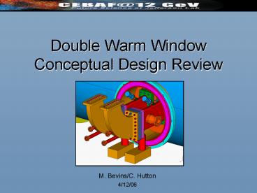
Double Warm Window Conceptual Design Review - PowerPoint PPT Presentation
1 / 23
Title:
Double Warm Window Conceptual Design Review
Description:
Fabricate and test prototype assembly on RF test stand (IR camera, vacuum characteristics) Fabricate two waveguide assemblies and mating dual top hat for HTB testing ... – PowerPoint PPT presentation
Number of Views:67
Avg rating:3.0/5.0
Title: Double Warm Window Conceptual Design Review
1
Double Warm WindowConceptual Design Review
- M. Bevins/C. Hutton
- 4/12/06
2
CONTENTS
- Objective
- Design Constraints
- Proposed Configuration
- Alternative Window Designs
- Where We Go From Here
- Comments, Concerns, Questions
3
OBJECTIVE
Incorporate a second warm window to establish a
UHV waveguide guard vacuum space employing
knife-edge sealing technology in the 12GeV
cryomodule.
- Design efforts began 1/4/06
- Near term goal develop conceptual design by
4/1/06
4
DESIGN CONSTRAINTS
Hard constraint was placed on ability to seal
cavity string vacuum in clean room prior to
assembly into vacuum vessel.
Vacuum Vessel ID
Double-sealing warm window flange required
Limited space requires in-line double-sided
knife-edge window flange.
5
DESIGN CONSTRAINTS
Current Warm Window Flange
- Flange is not wide enough to accommodate 2nd
knife edge. - Requires change in width of ceramic window OR
change in width of the flange. - Strong desire to avoid changes to the RF design
drove decision to increase the width of the
flange.
Knife-edge seal to FPC flange
Eyelet Recess
6
DESIGN CONSTRAINTS
Maximum Width Dimension for First Window Flange
Renascence FPC 4 5 Spacing
- Driven by spacing between FPCs 4 5
- REN spacing already generates slight interference
between FPC warm flanges - Increased FPC 4 5 spacing by trading drift
length from one end to the other.
12GeV FPC 4 5 Spacing
Increased drift here
Decreased drift here
7
PROPOSED CONFIGURATION
Double-Sided Knife-Edge Flange Design
- Design constraints satisfied by modified
commercial rectangular UHV flange (Thermionics
Labs) - Allowed vendor to define the number, size and
spacing for the bolts and the knife-edge geometry
- at no cost to us! - Enabled us to continue with layouts for the
double window configuration in parallel with the
flange design.
- Cost for first article 960.00
- Price drops by more than factor of 2 for qty
above 5
Outside Dimensions 3.78in x 7.62in x 1.36in
8
PROPOSED CONFIGURATION
Top hat (instrumentation will have separate
dedicated feed through)
Double-sided window flange
9
PROPOSED CONFIGURATION
Flange to 1st (inner) window flange
1-1/3 mini Conflat Inst. Port (IR)
Flange to 2nd (outer) window flange
Cu plated SS Tube (inside dimensions match FPC)
2-3/4 Conflat Vacuum port
1-1/3 mini Conflat Inst. Port (ARC)
10
PROPOSED CONFIGURATION
- RF Shield
- Holes bored into wall of waveguide
- Radius inside edge of holes
2.5 OD tube
RF shield holes
Inside weld
11
PROPOSED CONFIGURATION
IR sensor
Vacuum pump port
2nd warm window flange
Air side waveguide (same position as SL21)
Arc detector
12
PROPOSED CONFIGURATION One Pump per Waveguide
Roughing valve
- Vacuum Analysis
- Desire lt10-8 torr
- System will be baked
- Assumed 2.510-11 torr-liter/s/cm2 outgassing
- Guidance for conductance calcs from J.M.
Lafferty, Vacuum Science text - Delivered speed 18 L/s
- Allows for gas load of 210-7 torr-liter/s
(margin of 5)
30L/s Ion pump
13
PROPOSED CONFIGURATION
14
PROPOSED CONFIGURATION
15
PROPOSED CONFIGURATION
Overall Layout
16
PROPOSED CONFIGURATION
- Waveguide support brackets
- Stainless steel construction
- Goal - minimize features that must be controlled
- Provides translation and rotation in all six dof
- Provides allowance for full top hat float
17
PROPOSED CONFIGURATION
18
PROPOSED CONFIGURATION
19
PROPOSED CONFIGURATION
Tunnel Installation
- Module is narrower than CEBAF design
- Complete double window waveguide assembly can be
installed in test lab
20
ALTERNATIVE WINDOW DESIGNS 1 of 2
- Explore brazing eyelet and ceramic into
stainless steel adapter - Separates braze and flange sealing challenges
- Adapter would be welded into flange
Ceramic
Eyelet
Double-sided flange
Adapter
21
ALTERNATIVE WINDOW DESIGNS 2 of 2
Explore Thermally Matched Tungsten-Copper
Pseudo-Alloy Flange Design
- Methods used in semiconductor industry for many
years - Tune WCu CTE by adjusting Cu fraction
- WCu CTE 6.5-8.3 ppm/K (10-20 Cu)
- Alumina CTE 6.7-7.4 ppm/K
- As-sintered hardness gt170 BHN for 20 Cu fraction
- Eliminates need for eyelet
- Thermal conductivity gt170 W/m/K
- Material cost per flange 625.00 (430.00 for
larger qty) - Very preliminary temperature stress analysis is
encouraging
22
WHERE WE GO FROM HERE
- Procure flanges for testing to evaluate
rectangular knife-edge sealing reliability - Complete detail design of waveguide assembly
- Fabricate and test prototype assembly on RF test
stand (IR camera, vacuum characteristics) - Fabricate two waveguide assemblies and mating
dual top hat for HTB testing - Continue to explore (in parallel with other
efforts) alternative window designs - Procure WCu for testing
23
COMMENTSCONCERNSQUESTIONS


