
Computer Vision Projects B.J. Guillot Presentation Date 1242001 - PowerPoint PPT Presentation
1 / 19
Title:
Computer Vision Projects B.J. Guillot Presentation Date 1242001
Description:
A Multi-Ring Color Fiducial System and a Rule-Based Detection Method for ... Dynamic Workspace Extension in Video See-Through Self-Tracking Augmented Reality' ... – PowerPoint PPT presentation
Number of Views:158
Avg rating:3.0/5.0
Title: Computer Vision Projects B.J. Guillot Presentation Date 1242001
1
Computer Vision ProjectsB.J. Guillot
(Presentation Date 1/24/2001)
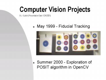
- May 1999 - Fiducial Tracking
- Summer 2000 - Exploration of POSIT algorithm in
OpenCV
2
Fiducial Tracking references
- CHO98 Cho, Youngkwan, Jongweon Lee, and Ulrich
Neumann. "A Multi-Ring Color Fiducial System and
a Rule-Based Detection Method for Scalable
Fiducial-Tracking Augmented Reality". November
1998. http//www.usc.edu/dept/CGIT/papers/cho-lee
-IWAR98.pdf - CHO97 Cho, Youngkwan, Jun Park, and Ulrich
Neumann. "Fast Color Fiducial Detection and
Dynamic Workspace Extension in Video See-Through
Self-Tracking Augmented Reality".October 1997.
http//www.usc.edu/dept/CGIT/papers/PacificGraphic
s98-AR.pdf
3
Processing Flow
- Grab a frame from the camera
- Create horizontal line segments every N
horizontal scan lines (low resolution pass) - Grow regions around blue line segments
- Form bounding rectangles around these coarse
regions - Refine the region size and position using full
pixel count inside the bounding rectangles (high
resolution pass) - Square regions are the targets
- Loop back to the top
4
Horizontal Line Segments
- This function scans every nth horizontal scan
line looking to break the lines up into segments
of like colors - The segments are broken with a form of edge
detection using a color distance metric based
upon the square of the color angle cosine
5
Square of the color angle cosine pseudo-code
implementation
- Boolean hitEdge(inputs left and right color
components) - numerator
- (leftRedrightRed leftGreenrightGreen
leftBluerightBlue)2 - denominator
- (leftRed2 leftGreen2 leftBlue2)
- (rightRed2 rightGreen2 rightBlue2)
- if (denominator 0) return(FALSE)
- distance numerator / denominator
- if (distance lt DISTANCE_THRESHOLD) return(TRUE)
else return(FALSE)
6
Region growing Bounding Rectangles
- The system was designed to look for regions that
had a large blue intensity component
7
Refinement of Bounding Rectangles
- All pixels inside the bounding rectangle are used
(high res pass) to refine the size and position
of the rectangle by determining separating the
background color from the blue-colored target
8
Identification of centroid
- After bounding box refinement, we can guess we
are looking at a blue-colored target if the new
bounding rectangle is approximately square.
(The program will not handle circles not directly
perpendicular to the camera--they will appear an
ellipses and therefore will not be detected.) - A crosshair can be drawn over the original video
images targets to produce an augmented reality
image
9
Real examples
10
POSIT reference
- DeMenthon, Daniel F. and Davis, Larry S.
Model-Based Object Pose in 25 Lines of Code.
http//www.cfar.umd.edu/daniel/daniel_papersfordo
wnload/Pose25Lines.pdf - POSIT POS IT
- POS Pose from Orthography and Scaling
- IT with Iterations
11
POSIT description
- Method for finding the pose of an object from
single image - Assumption We can detect and match in the image
four (or more) noncoplanar feature points of the
object, and that we know the relative 3D geometry
of the object - POS Approximates the perspective projection with
a scaled orthographic projection and finds the
rotation matrix and the translation vector of the
object by solving a linear system - POSIT Uses in its iteration loop the approximate
pose found by POS in order to compute better
scaled orthographic projections of the feature
points, then applies POS to these projections
instead of the original image projections.
12
POSIT advantages
- More than 4 points can be used for added
insensitivity to measurement errors and image
noise - Classic approach uses Newtons method and
requires an initial pose estimate POSIT does not
require this and uses an order of magnitude fewer
floating point operations (10x faster) - Suitable for real-time operation
- Algorithm can be written in 25 lines of code
(Mathematica)
13
Review Orthographic vs. Perspective Projections
- In orthogonal views, the projectors are
perpendicular to the projection plane.
Orthographic views preserves both distances and
angles, and because there is no distortion of
either distance or shape, orthographic
projections are well suited for working drawings.
- Perspective views are characterized by diminution
of size. When objects are moved farther from the
viewer, their images become smaller. The size
change gives perspective views their natural
appearance. Because the amount by which the line
is foreshortened depends on how far the line is
from the viewer, we cannot make measurements from
a perspective view. The major use of perspective
views is in applications like architecture and
animation, where it is important to achieve
real-looking images.
14
Examples using OpenCV
- User picks cooresponding points from a 3D model
and a 2D image program then overlays 3D
wireframe model on top of 2D image
15
POSIT usage example
- CvPoint2D32f points2D //must be populated
before calling POSIT - CvPoint3D32f points3D //must be populated
before calling POSIT - //should be a 11 binding bwtn 2D 3D
points - CvPOSITObject pObject //posit object
- CvMatrix3 rotationMatrix //posit-returned
rotation matrix - CvPoint3D32f translationVector //posit-returned
translation vector - pObject cvCreatePOSITObject(points3D,
num3dPoints1) //make sure not null - //set posit termination criteria 100 max
iterations, convergence epsilon 1.0e-5 - CvTermCriteria criteria cvTermCriteria(CV_TERMCR
IT_EPS, 100, 1.0e-5) - cvPOSIT(points2D, pObject, FOCAL_LENGTH,
criteria, rotationMatrix, translationVector) - cvReleasePOSITObject(pObject)
- In order to make use of the returned matrix and
vector with OpenGL, we must do some quick
adjustments...
16
POSIT usage example, continued...
- //populate opengl-compatible matrix from posit
rotation matrix and translation vector - GLfloat positMatrix16
- positMatrix0 rotationMatrix.m00
- positMatrix1 rotationMatrix.m10
- positMatrix2 rotationMatrix.m20
- positMatrix3 0.0 //homogeneous
- positMatrix4 rotationMatrix.m01
- positMatrix5 rotationMatrix.m11
- positMatrix6 rotationMatrix.m21
- positMatrix7 0.0 //homogeneous
- positMatrix8 rotationMatrix.m02
- positMatrix9 rotationMatrix.m12
- positMatrix10 rotationMatrix.m22
- positMatrix11 0.0 //homeogenous
- positMatrix12 translationVector.x
- positMatrix13 translationVector.y
- positMatrix14 -translationVector.z
//negative - positMatrix15 1.0 //homogeneous
17
Example using VRML model of space shuttle
- Overlay did not line up points chosen were left
and right wing tips, tail, and nose. - Overlay lines up with the tail and right wing
tip, but not with the left wing tip and nose!
18
Second try...
- We still have the problem here the same points
were selected along with two additional (the two
overhead windows), but in this case, the
alignment with the tail and right wing is not as
good as the previous attempt
19
Other OpenCV experiments
- Study of the calibration filter attempting to
modify is more of an exercise in MFC/Visual C
than Computer Vision
Recommended
CrystalGraphics Presentations


