Enhanced Ion Tweeter - PowerPoint PPT Presentation
1 / 16
Title:
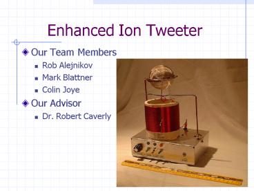
Enhanced Ion Tweeter
Description:
Enhanced Ion Tweeter. Our Team Members. Rob Alejnikov. Mark Blattner. Colin Joye. Our Advisor ... Ion tweeter cannot implement low frequencies -- Filter ... – PowerPoint PPT presentation
Number of Views:103
Avg rating:3.0/5.0
Title: Enhanced Ion Tweeter
1
Enhanced Ion Tweeter
- Our Team Members
- Rob Alejnikov
- Mark Blattner
- Colin Joye
- Our Advisor
- Dr. Robert Caverly
2
Project Objectives
- What did we do?
- Created an audio transducer that offers the same
frequency content in all directions. - Concentrated on high frequencies since they tend
to beam the most. - How we did it The Ion flame
- What is it?
- Voltage -- flame size -- sound
- Existing devices use vacuum tubes, creating
excessive heat - Goal
- Raise power efficiency
- Decrease unit cost
3
Presentation Objectives
- Intro, Audio Subsystem Rob
- High Voltage Generation Mark
- Results and Conclusions Colin
4
The Audio Subsystem
- Need
- Ion tweeter cannot implement low frequencies --
Filter - Output of source device (CD, cassette) up to 1 V
power rail modulation requires 30 V -- Gain - Design Criteria
- Flat frequency response for high audio
frequencies - Sufficient gain on signal passed to high voltage
circuit
5
The Audio Subsystem
- 3-stage implementation
- Buffer for high input impedance
- Low Pass
- High Pass
- Performance measures
- Cutoff at 4 kHz and 40 kHz
- Total gain factor up to 60
6
High Voltage Circuit Operation
- Generates high voltage necessary for Corona
Discharge - Major Components
- Power MOSFET
- MOSFET Gate Driver
- Coil
- Uses Resonant Properties of Coil to produce High
Voltages - Self-Oscillating nature of circuit provides
resilience to environmental changes
7
Coil Implementations
- Keys to producing High Voltage
- Resonant Frequency between 3MHz and 8MHz to avoid
audible hiss and limitations of technology - High Quality Factor (Q) causes near open circuit
- Low DC resistance
8
Coil Implementations
- 10 Coils Built and Tested
- Built with Varying Specs
- Dimension, wire gauge, and number
of turns - Coil Chosen
- 16 Gauge Wire
- 45 Turns
- 5 MHz Resonance
- D3 H2.5
9
Field Effect Transistor (FET)
- FET rapidly switches a small current in the coil.
- Optimal FET
- High Voltage handling
- 500 volts
- High Transconductance
- Greater current in coil
- Low Gate Capacitance
- Reduces stress on Gate Driver
10
Interface Methods
- Numerous Approaches Tried and Tested
- Pulse Width Modulation (PWM) via Gate Driver
- Power Rail Modulation via Audio Transformer
- Ground Rail Modulation via Audio Transformer
- Faraday Shield Modulation
11
Interface Methods
- Decided on Power Rail Modulation
- PWM unable to obtain clean waveforms and
oscillations - Faraday Shield requires very High Voltages
12
Noise versus Coil Frequency
- Flame Flicker Noise present up to 3MHz, as noted
by Siegfried Klein in 1956. - This noise is virtually inaudible 7MHz and up.
- At 30MHz, the flame has a different appearance
and no noise.
13
Testing
- Power Efficiency Test
- Tube-based
- 114W at 1cm flame height.
- FET-based
- 67W at 1cm flame height.
- 40 Power savings
14
Unit Cost
- Unit Cost (45 savings)
- FET 48.46 (to us), 65.44 (industry)
- Tube 120.53
- Total man-hours
- 750 man-hours
- Estimated industry cost
- 45,270
15
Recommendations
- For Increased Linearity
- Pulse Width modulation of the FET.
- Requires high speed, high precision circuitry.
- Requires virtually zero extra power.
- Occupies almost no space.
- Faraday Shield Modulation.
- Affects the voltage gradient directly.
- Requires high voltage audio.
- Increase operation frequency
- Increase flame power
16
In Conclusion
- Special Thanks to
- Texas Instruments (gate drivers)
- BGR-WYK Distributors (ST FETs)
- International Rectifier (FETs)
- Fairchild Semiconductors (FETs)
- Alpha Industries (diodes)
- Join us for a demo in CEER 210.
- Questions????


