Structural modeling system - PowerPoint PPT Presentation
1 / 22
Title:
Structural modeling system
Description:
VM. Cable 1. Cable 2. The objects are created to simplify the further modeling ... continuation of work on finishing the creation of a universal translator, ... – PowerPoint PPT presentation
Number of Views:61
Avg rating:3.0/5.0
Title: Structural modeling system
1
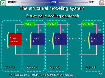
The structural modeling system
Structural modeling approach
The objects are created to simplify the further
modeling
2
The mathematical principles of modeling system
Mathematical methods
Differential equation solving
Solution parameter estimation
Prediction - correction
Runge - Kutta method
Non-linear system error
Extrapolation
Newton method with inverting matrix
Difference system stability
Prognosis - correction
3
The Runge-Kutta method solution on the parallel
system
The K coefficients are calculated in
parallel At the calculation of link functions all
another calculations are suspended before getting
a new value of j
4
The modeling system structure
Object description in the kind of differential
equation system
Object library
The object
User
Object connection scheme
C - program
Executable file
Simulation result table
Compiler CL30 Linker LNK30
Simulation result diagram
5
The interactions between objects in the modeling
system
1. The separate modeled objects are independent
from each other, the any link between them is
absent
2. The objects are connected among themselves
by transmission line of energy, and cooperate
with each other in a direction of energy
distribution
3. The objects are connected tightly with each
other, thus there are the feedback chains, in
which the interaction is opposite to a direction
of an energy distribution vector
6
The library structure for the modeling system
Library name
Object name
Input variables
Output variables
Control equations
State equations
Pre-calculated data
7
Multiprocessor computing system
512Kx32 GLOBAL BUS
512Kx32 LOCAL BUS
512Kx32 GLOBAL BUS
512Kx32 LOCAL BUS
512Kx32 LOCAL BUS
512Kx32 GLOBAL BUS
512Kx32 LOCAL BUS
512Kx32 GLOBAL BUS
4 1 TMS320C44 5 2
4 1 TMS320C44 5 2
4 1 TMS320C44 5 2
4 1 TMS320C44 5 2
Link 5
Link 2
Link 1
2xFIFO 1Kbyte
JTAG Controller
HOST Interface
Fixed links
HOST ISA BUS
User links
8
The challenge problem task
Electrical circuit
Equations
R3, R31, R32 - circuit breakers
Rk - short circuit resistance during
line-to-ground fault at the 15s after start
Main task is to simulate the circuit behavior
from start till 25s of working
9
The challenge problem solving with Runge-Kutta
method
Equation distribution between the processors
Interchanges between the processors
10
The electric circuit division for Gauss-Siedel
method in the object form
Object distribution between the processors, each
part is the complex logical object
11
The coupling method realization
The coupling method
The modified coupling method
12
The challenge problem solving with Gauss-Siedel
method in the object form
Equation distribution between the processors
Interchanges between the processors
13
The challenge problem modeling result (general)
Generator current (I), voltage (V) and angular
speed (Omega) from 0s till 25s
14
The challenge problem modeling result (detailed)
Generator current (I), voltage (V) and angular
speed (Omega) from 14.9s till 15.3s
15
Multiprocessor computing system gain
Gain
The challenge problem solving with the
Runge-Kutta method Best time is 160s
1 2 4 Processor quantity
Gain
The challenge problem solving with the
Gauss-Siedel method Best time is 110s
1 2 Processor quantity
16
The existing modeling system
17
The requirements to the perspective test bed
1. High processor performance (min. 100MIPS and
200MFLOPS) 2. Full hardware support of base
operations 3. High speed of interprocessor data
exchange (min. 300MB/sec) 4. Large volume of
local processor memory (min. 256MB) 5. Full
support of IEEE 754 standard 6. Presence of
high-speed universal interprocessor commutator
(crossbar) 7. Presence of high-speed exchange
channel with external devices 8. Scalable
multiprocessor architecture
18
The quadrant architecture
Processor 1
Processor 2
Processor 4
Processor 3
Transfer controller
Commutator (crossbar)
Local memory Bank 1
Local memory Bank 2
Local memory Bank 4
Local memory Bank 3
19
The perspective test bed architecture
Quadrant 1
Quadrant 2
Quadrant N
Transfer controller
Commutator (crossbar)
Global memory Bank 1
Global memory Bank 2
Global memory Bank N
External devices
20
The procedural-structured modeling system
21
The cross-assembler for structural programs
Language gramma
Cross- assembler
Abstract model
Level of abstract description
Object code for multiprossesor system
Objects Library
22
The perspectives
1. The development of mathematical base of
problem-oriented task modeling by
parallel methods with the structured
decomposition of task.
2. Undertaking the studies in the field of MCS
building and the synthesis of multiprocessor hardw
are for the future test bed with the optimum
efficiency.
3. The creation of hardware-independent software
structured programming system, allowing to
automate the programming process on parallel
hardware of test bed.
4. The development of structured programming
language, which is invariant for
available equipment of the multiprocessors.
Forming a library of structured models, oriented
on electrical networks, continuation of work on
finishing the creation of a universal
translator, allowing to combine the procedural
and structured programming methods, and to
ensure succession of preceding program
developments on models of electrical network.
5. The development of assembler for
structured-procedural calculations, allowing
to generate the procedural programs from the
traditional high level languages and
structured programs from structured programming
language, which allows to realize the
structured support of procedural program
(acceleration) and the procedural support of
structured programs at the deficit of
multiprocessor equipment.


