RF technology workshop, Amsterdam, October 4 - PowerPoint PPT Presentation
1 / 6
Title:
RF technology workshop, Amsterdam, October 4
Description:
All current activity revolves ... Main design challenge is reduction of heat load through: ... Increasing Din Spot size increases which lowers power density ... – PowerPoint PPT presentation
Number of Views:37
Avg rating:3.0/5.0
Title: RF technology workshop, Amsterdam, October 4
1
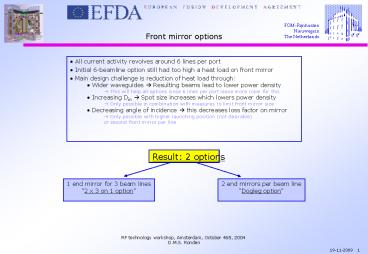
- All current activity revolves around 6 lines per
port - Initial 6-beamline option still had too high a
heat load on front mirror - Main design challenge is reduction of heat load
through - Wider waveguides ? Resulting beams lead to lower
power density - ? This will help all options since 6 lines per
port leave more room for this - Increasing Din ? Spot size increases which
lowers power density - ? Only possible in combination with measures to
limit front mirror size - Decreasing angle of incidence ? this decreases
loss factor on mirror - Only possible with higher launching position
(not desirable) - or second front mirror per line
Result 2 options
1 end mirror for 3 beam lines 2 x 3 on 1 option
2 end mirrors per beam line Dogleg option
2
2 x 3 on 1 option
3
2 x 3 on 1 option
- Pros
- Smaller end mirror surface when wider waveguides
are used. This leads to a lower heat load on the
end mirror.
- Cons
- Since each end mirror controls three beams,
there is less freedom in aiming the beams slight
variation in Alpha / Beta angle. - Mirrors most likely grow larger in length than
earlier options with 1 line per mirror. - Hole in front shield needs to be higher then
earlier 6-beamline option. However, it can be
more narrow. - Placing the components at rear end of the port
plug will prove to be difficult.
4
Dogleg option
5
Dogleg option
- Pros
- Launching positions can be placed lower and
closer to the front shield - Dog leg drastically reduces neutron streaming
towards rear end of the plug, since waveguides do
not face the plasma - Front shield penetration is much smaller
- Mirrors are a lot smaller and are therefore
easier to handle - Less problems with placing components in the
launcher interspace in the rear. - Cut in lower blanket module is not required
- First mirror after waveguide can be used for
both upper and lower row - More flexible design due to increased number of
parameters - Scanning range through waveguide can be lower
(/- 10 deg) for at least three beamlines
- Cons
- 9 Mirrors are required in the front shield,
which leads to a higher amount of total power
that needs to be cooled away - Scanning range measured in degrees is larger
then with any other option this requires a
higher degree of accuracy in the steering
mechanism and mirror surfaces. - Less shielding can be realised for area above
the port plug, as compared to previous options. - ? There is still some room for further
optimisation
6
Qualitative comparison
Blue 6 beamline option Purple 2 x 3 on 1
option Green Dogleg option
Conclusion When comparing nominal spot sizes on
the absorption plane, it appears that the dogleg
option outperforms all recent launcher options! ?
More time is needed to do exact calculations to
determine the overall performance

