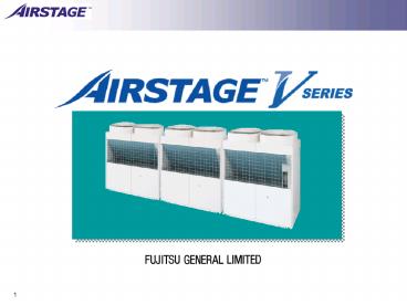
V series feature - PowerPoint PPT Presentation
1 / 28
Title:
V series feature
Description:
TH1. SV. TH Ts 12 Gas Phase refrigerant. TH Ts 12 Liquid ... TH1. SV. Liquid seal in liquid line to Indoor unit. Stable operation. Increase the capacity ... – PowerPoint PPT presentation
Number of Views:42
Avg rating:3.0/5.0
Title: V series feature
1
1
2
V series feature
1
3
DC Inverter Control Compressor
Key point - 2
The introduction of DC inverter compressors and
the control technology provides more precise
operation, improving system efficiency.
V series
Conventional model
Compressors
Compressors
Constant speed comp.
Constant speed comp.
Constant speed comp.
Constant speed comp.
DC Inverter comp.
Constant speed comp.
HIGH EFFICIENCY OPERATION
5
4
HIGH RELIABILITY
HIGH RELIABILITY
Compressor rotation control
Improvement of long life by reducing compressor
wear
Compressor starting rotation (Constant speed)
Inverter comp.
Constant speed comp.
10
5
HIGH RELIABILITY
HIGH RELIABILITY
Emergency operation (Outdoor unit)
Continuous operation is possible even in the
unlikely event of compressor failure
Slave unit
Slave unit
Master unit
Note These compressor configuration is shown by
14HP outdoor units.
11
6
HIGH RELIABILITY
HIGH RELIABILITY
Emergency operation (Indoor unit)
Continuous operation is possible even if trouble
occurs at an indoor unit
12
7
HIGH RELIABILITY
HIGH RELIABILITY
Optimum oil control
Stable operation of compressor by optimum oil
control
Oil separator
Oil equalization pipe
High trapping efficiency, large capacity cyclone
type oil separator
1
2
Oil balance control which maintains uniform oil
levels
3
Optimum EEV control for oil and refrigerant
circulation
13
8
HIGH EFFICIENCY OPERATION
HIGH EFFICIENCY OPERATION
Effective use of the heat exchanger of other
outdoor units
This system takes advantage of the features of
the multi type outdoor unit
The larger heat exchanger than the capacity of a
compressor is used in each outdoor unit. (V
series)
Example
Conventional method
20
9
HIGH EFFICIENCY OPERATION
HIGH EFFICIENCY OPERATION
High efficiency outdoor unit
Large propeller fan
Equipped with DC inverter scroll compressor
Adopted Sine-wave DC inverter control
14HP (Master unit)
Sine-wave DC Inverter Control
DC inverter Scroll compressor
22
10
HIGH EFFICIENCY OPERATION
HIGH EFFICIENCY OPERATION
High efficiency
All key features of the outdoor unit result in a
higher level of COP
3.2
Cooling COP
3.7
Heating COP
The data refers to a 10HP outdoor unit. COP
is the coefficient of performance capacity
(kW) input power (kW). COP values are base
on our own testing method.
21
11
Comparison with S series
High Efficiency Refrigerant R410A
Enlarge Heat Ex
Light Weight
DC Inverter 3 ?2 Compressor
Blue Fin Coating
Size down
12
INDOOR UNIT CONTROL
- Improve the comfort
S series
EEV Control by Temperature Control 1?
Setting Temp Room Temp
THmed
FIXED PULSE control (Normal operation)
HEX
V series
THin
EEV Control by Super Heat (SH) Control
SHTHout Thin Temperature Control 0.5?
THout
HEX
Target SH control Auto PI EEV control
Optimize EEV control for cooling performance and
room temperature control. Equalize the capacity
balance for each indoor unit.
13
Smooth Control
- Compressor Control
S series
Combination of 3 constant speed Compressor. (7
Steps)
Capacity loss has made between
each steps
V series
Target pressure control
Combination of DC Inverter and constant speed
Compressor. (Linear Steps)
Prevent Frequency ON/OFF
14
Liquid level sensor
Discharge Pipe
TH gt Ts 12 Gas Phase refrigerant THlt Ts
12 Liquid Phase refrigerant
- By keeping liquid level on Receiver Tank
- refrigerant balance control between outdoor unit
- Stable operation by liquid line
15
SUBCOOL HEX CIRCUIT
- Liquid seal in liquid line to Indoor unit
- ?Stable operation
- Increase the capacity
- Reduce unpleasant noise
16
Non stop oil recovery
- Keep the cooling operation while oil recovery
S series
Oil Recovery
ON
Compressor
OFF
ON
Indoor Unit
OFF
Cooling operation stop whole system cause to
temperature rise during oil recovery operation.
Oil Recovery
V series
ON
Compressor
OFF
ON
Indoor Unit
OFF
Non
Stop
?Heating mode is stopped at before and after.
17
Sine wave inverter
- Sine wave vector control
Objectives 1. Reduce vibration
and noise by changing to smooth conduction. 2.
Improve efficiency by reducingharmonics.
18
High Efficiency Pass
Current model
New model
Air flow
Improved pass balance
19
Blue Fin Treatment
Anti corrosive treatment
Blue fin heat exchanger
20
Delay start
3 sec interval for each compressor
DIP SW setting switch to delay 3 steps
21sec / 42 sec / 63 sec
21
Permanent stop for emergency
Protect the second serious accident
When following error generated, outdoor unit
Become to stop permanently.
Low pressure error Pressure sensor error 4 way
valve error etc,.
System have to be released error by Power
reset and Set Error Reset (DIP-SW) .
22
Drain Pan Cleaning
- Easy to clean
- and take out
- Fallen leaves
23
Address setting
Address setting can be done by wireless remote
controller
24
Various Duct
- Low Static Pressure Duct
Duct
25
Compact design
ARXC36-60
26
Compact wall mounted
Low Noise (External EV KIT)
- FILTER
Wired RC
27
Pipe size has been reduced
- Pipe Size
Improving the installation by the piping size
down
28
Pipe size has been changed
- Pipe Size
Indoor unit Model code
Blazing
Pipe size increased to reduce the pressure loss


![READ⚡[PDF]✔ Panpsychism: Contemporary Perspectives (Philosophy of Mind Series) PowerPoint PPT Presentation](https://s3.amazonaws.com/images.powershow.com/10050356.th0.jpg?_=20240607116)


