Digital Elevation Models DEM - PowerPoint PPT Presentation
1 / 24
Title:
Digital Elevation Models DEM
Description:
stereo photos - contour lines - digitised lines - convert ... Tanaka relief contours not a common software option. Slope and aspect layers (GIS analysis) ... – PowerPoint PPT presentation
Number of Views:3028
Avg rating:3.0/5.0
Title: Digital Elevation Models DEM
1
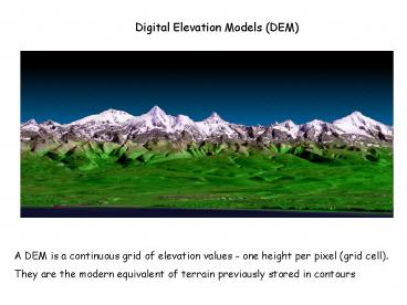
Digital Elevation Models (DEM)
A DEM is a continuous grid of elevation values -
one height per pixel (grid cell). They are the
modern equivalent of terrain previously stored in
contours
2
DEM creation
- by digitising contours (e.g. NTS maps -gt NTDB
layer). - This is 'second hand' digital, as contours are
abstract and may result in 'artifacts' in the
model. - stereo photos -gt contour lines -gt digitised lines
-gt convert to raster GRID - B. Digital stereo photogrammetry (e.g. BC TRIM)
- This is a better option, as it refers to the real
surface, captured from aerial photographs - stereo photos -gt mass points -gt convert to raster
GRID - C. Direct image grid DEM (new millenium)
- Newer techniques creating DEM grids directly have
multiplied since 2000 - Note GPS can be used to collect elevation
points, that can supplement a DEM (or create
small ones)
3
Air Photo -gt DEM -gt
Shaded relief
4
SRTM (Shuttle Radar Topographic Mission) 90
metre pixels, 60ºS-60ºN
5
LiDAR Ground zero
6
ASTER
7
Ikonos 5m
8
DEM data availability
DEMs have been created at a variety of scales by
different agencies. Some can be downloaded free
(see lecture on digital data)
-gt www.geobase.ca
SRTM 1 100,000
90
9
Impact of DEMs on relief depictionContour lines
can be interpolated from DEM heights or pre-exist
from digitised maps, and are a standard layer in
digital databases and online web mapping for
display.
10
Hypsometric TintsSelection of hues, chromas from
colour sequences
Default Arcmap tints legend
11
Shaded relief No longer does the practitioner
require artistic ability. The user selects
azimuth and zenith, 315/ 45 to match the NW light
source. It is easily generated but artifacts
appear if the data are flawed or sparse. The
results may not be as good as from a skilled
manual practitioner
12
Using the transparency option for shading and
tints
13
Manual versus digital shading ?
Manual 1981
Digital 2001
14
Tanaka relief contours not a common software
option
15
Slope and aspect layers (GIS analysis)
16
3D perspectives
Perspectives are produced by GIS and
visualization software. The user selects
parameters such as viewing angle, vertical
exaggeration and what may overlay the terrain,
such as a 'draped' aerial photograph (e.g. google
earth), scanned map or layers.
17
Rocky Mountain trench Castle Creek Glacier
18
http//www.earthdetails.com/
19
3D anaglyphs
20
Animations http//asterweb.jpl.nasa.gov/gallery/i
mages/msh.mpg
21
http//www.davidrumsey.com/GIS/3D.htm
22
Summary
3D perspectives along with hill-shading have seen
the greatest increase in use with automation -gt
easily done, visual, previously time-consuming
23
JLC Geomatique
24
(No Transcript)


