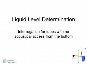
Liquid Level Determination
1 / 12
Title: Liquid Level Determination
1
Liquid Level Determination
- Interrogation for tubes with no acoustical access
from the bottom
2
Technique for LLD
- Ideally, LLD could be performed from the
bottomsimple design, no moving parts - But, the Abgene tube has an air gap in the bottom
requiring interrogation from the side - If a single detector is used, either the tube or
detector must be moved up and down the tube
3
Use of a Single Detector for LLD
- The use of a single element 5 MHz ultrasonic
transducer has been evaluated - A Pulser/Receiver circuit board has been built to
drive the transducer - RS232 serial communication is used between the
board and a PC - Sample driver software to drive the board has
been written in Labview
4
Parameters for the Pulser/Receiver
- The board acquires at 100 MS/s.. 10 ns/S
- Gain adj over 40 db setting 0 to 255
- Resolution 8 or 10 bits
- Acquisition immediately begins at software
trigger - Number of Points Acquired 32,000
- First point transferred to PC 1 to 32,000
- Number of points transferred 1 to 32,000
- Address Increment adjustable 1 to 10
5
Typical Initial Setup Parameters
- The following are what is adjustable using the
S cmd - Gain 80
- Res 8 (one byte, rather than two)
- 1st Point 8800 (ie, 88 us after xmt pulse)
- Num Pts 200
- Add Inc 2 (giving effectively, 20 ns/S res)
6
An Alignment Procedure
- Start the initial system alignment (diff for each
tube type? every 24 hrs?) - Position the front wall of an empty Abgene tube
65 mm from transducer - Fine tune the range position so that the echo
minimum is at point 80 - Fine tune the transverse position so that the
echo minimum is as small as possible - Adjust the gain so the echo minimum 40 -5
7
Echos when the acoustic beam is above and below
the liquid level
8
Algorithm for LLD from the echo
- The initial few cycles are from the interface
between the water and the first surface of the
front-wall - When the beam is above the LL, air is behind the
front-wall and gives the large echo cycles at the
end - When the beam is below the LL, water is behind
the front-wall and gives the small echo cycles at
the end
9
Algorithm for LLD from the echo (cont)
- The ratio of the minimum of the whole echo to the
3rd minimum is high when the acoustic axis is
above the LLand is unity when below the LL
10
Algorithm for LLD from the echo (cont 2)
- Typical ratio of mins as more and more water is
removed from a tube in 10ul increments
11
Calibration Process
- With an empty tube scan from the bottom up.
- Note z coor when ratio rises to 1.5. This is vol
0. - Then the calibration curve can be used to
determine the volume in a tube that is placed in
the same initial position and lowered until the
ratio rises to 1.5
12
Liquid level data


