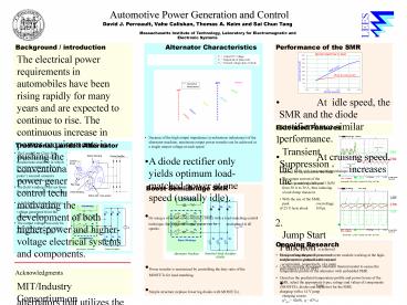
Performance of the SMR - PowerPoint PPT Presentation
1 / 1
Title:
Performance of the SMR
Description:
Massachusetts Institute of Technology, Laboratory for Electromagnetic and ... is suddenly reduced from 50 A to 30 A, thus inducing a load dump transient. ... – PowerPoint PPT presentation
Number of Views:63
Avg rating:3.0/5.0
Title: Performance of the SMR
1
Automotive Power Generation and Control
LEES
David J. Perreault, Vahe Caliskan, Thomas A. Keim
and Sai Chun Tang Massachusetts Institute of
Technology, Laboratory for Electromagnetic and
Electronic Systems
Performance of the SMR
Alternator Characteristics
Background / introduction
The electrical power requirements in automobiles
have been rising rapidly for many years and are
expected to continue to rise. The continuous
increase in power requirements is pushing the
limits of conventional automotive power
generation and control technology, and is
motivating the development of both higher-power
and higher-voltage electrical systems and
components. Here we introduce a new design for
automotive alternators that utilizes the
conventional Lundell machine but incorporates a
simple switched mode rectifier along with a
special load-matching control technique. The new
design allows much higher levels of output power
and efficiency to be achieved as compared to
conventional designs while retaining low cost and
simplicity of structure and control.
Vo Output DC voltage Vs Magnitude of phase
emf Vd forward voltage drop of diode
At idle speed, the SMR and the diode
rectifier have similar performance. At
cruising speed, the SMR with load-matching
technique increases the power capability to 3.3kW!
Extended Features
1. Transient Suppression is achieved by the
control of the SMR. The output current of the
system is suddenly reduced from 50 A to 30 A,
thus inducing a load dump transient. With the
use of the SMR, peak overvoltage of 25 V lasts
about 100ms. 2. Jump Start Function is achieved
by connecting the machine neutral and the system
ground to the ve and ve terminals,
respectively, of a jump start source (14V or
28V). Jump charging with a 14 V jump
charging source. (Pout 920W, h 87)
Because of the high output impedance
(synchronous inductance) of the alternator
machine, maximum output power transfer can be
achieved at a single output voltage at each
speed. A diode rectifier only yields optimum
load-matched power at one speed (usually
idle). By using a switched-mode-rectifier (SMR)
with a load-matching control technique, the
alternator output power can be maximized at all
speeds.
Traditional Lundell Alternator
The Lundell, or Claw-Pole, alternator is a
wound-field synchronous machine in which the
rotor comprises a pair of stamped pole pieces
(claw poles) secured around a cylindrical field
winding. The field winding is driven from the
stator via a pair of slip rings. A
full-bridge diode rectifier is used to rectify
the 3-phase voltage generated from the alternator
machine. The output voltage can only be
controlled by the field current (slow transient
response).
horizontal 500 ms/div vertical 10 A/div, 10
V/div
Boost Semi-Bridge SMR
horizontal 5 ms/div vertical 20 A/div, 10 V/div
Ongoing Research
Design of an integrated power converter module
working at the high-temperature underhood
environment. Use the recently developed
alternator thermal model to assess the
temperature profile of the alternator with
embedded SMR. Based on the predicted
temperature profile and power losses of the SMR,
select the appropriate types, ratings and values
of components (MOSFETs, diodes and capacitor) for
the SMR.
Power transfer is maximized by controlling the
duty ratio of the MOSFETs for load-matching. Sim
ple structure (replace lower leg diodes with
MOSFETs). Simple control. Fast transient
response.
Acknowledgments
MIT/Industry Consortium on Advanced Automotive
Electrical/Electronic Components and Systems


