KState Channel Modeling Hardware
1 / 1
Title:
KState Channel Modeling Hardware
Description:
The hardware consists of two mixers, a summer, and a step-attenuator set. ... When used for frequency conversion, the mixer needs about 7 dBm of LO power. ... –
Number of Views:43
Avg rating:3.0/5.0
Title: KState Channel Modeling Hardware
1
K-State Channel Modeling Hardware
Quick Reference Guide
Main Components
This board contains most of the components needed
for basic channel modeling, including mixers, a
summer, and an attenuator. These parts are
described below. External signals, measurement
equipment, cables, and various frequency-specific
parts like lowpass filters may have to be added
depending on the experiment.
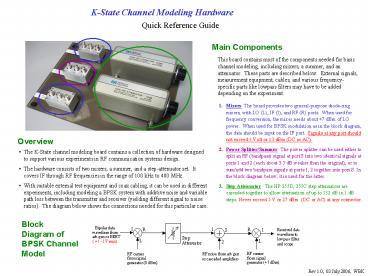
- Mixers The board provides two general-purpose
diode-ring mixers, with LO (L), IF (I), and RF
(R) ports. When used for frequency conversion,
the mixer needs about 7 dBm of LO power. When
used for BPSK modulation as in the block diagram,
the data should be input on the IF port. Signals
at any port should not exceed 1 Volt or 13 dBm
(DC or AC). - Power Splitter/Summer The power splitter can be
used either to split an RF (bandpass) signal at
port S into two identical signals at ports 1 and
2 (each about 3.5 dB weaker than the original),
or to sum/add two bandpass signals at ports 1, 2
together into port S. In the block diagram below,
it is used for the latter. - Step Attenuator The HP 355D, 355C step
attenuators are cascaded together to allow
attenuation of up to 132 dB in 1 dB steps. Never
exceed 5 V or 27 dBm (DC or AC) at any connector.
Overview
- The K-State channel modeling board contains a
collection of hardware designed to support
various experiments in RF communication systems
design. - The hardware consists of two mixers, a summer,
and a step-attenuator set. It covers IF through
RF frequencies in the range of 100 kHz to 400
MHz. - With suitable external test equipment and coax
cabling, it can be used in different experiments,
including modeling a BPSK system with additive
noise and variable path loss between the
transmitter and receiver (yielding different
signal to noise ratios). The diagram below shows
the connections needed for this particular case.
Block Diagram of BPSK Channel Model
Rev 1.0, 03 July 2006, WBK


