Folie 1
1 / 1
Title: Folie 1
1
Different ways to improve the cleanliness of the
sputter source in GD-OES systems
M. Aeberhard, T. Nelis, J. Michler, E.
Barisone EMPA, Swiss Federal Institute for
Materials Science and Technology,
Feuerwerkerstrasse 39, CH-3602 Thun, Switzerland
Laboratoire Laplace, Université Paul Sabatier,
118, Route de Narbonne, F-31062 Toulouse France
Glow discharge (GD) is a highly specialized
source that especially meets the requirements for
accuracy, simplicity and speed for content depth
profiling and bulk analysis in both Optical
Emission and Mass Spectrometry. The pulsed radio
frequency GD source has the potential for
elemental analysis of conductive and
non-conductive materials. For the analysis of
thin surface layers it is necessary to start with
a clean atmosphere inside the discharge cell. As
there is no shutter to close the anode after a
measurement it is quite difficult to prevent
atmospheric contamination (humidity, Hydrocarbons
and so on). How can we have clean conditions to
examine surfaces lt50nm? First tests where done
by measuring a Bulk sample of the same family as
the substrate of the sample to analyse. We chose
the same measuring time as we use for the
analysis. In this case, because the Oxide layer
we like to analyse is only 2nm thick, we measured
for 10 Seconds. This measurements were repeated,
until the Signal for Ar emission were stable
during the measurement time An other way of
improving the cleanliness is working with cooling
traps between the Vacuum Pumps and the Source.
The nitrogen cooling traps are used to prevent
the oil of the vacuum pumps from diffusing into
the discharge volume. These results are shown in
comparison with measurements performed under
same conditions other then the use of cooling
traps. Also a 10nm thick SiO2 layer on Silicon
was measured qualitatively with this cleaning
procedure. The time to purge the Lamp before
starting a measurement can be decreased by a
factor of 10 at least by working with cooling
traps.
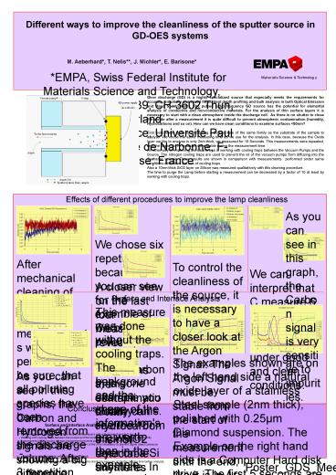
Effects of different procedures to improve the
lamp cleanliness
As you can see in this graph, the Carbon signal
is very sensitive to impurities.
We chose six repetitions because, as you can see
for the example of Carbon, the pollution for
Carbon (Hydrocarbons) is gone after 6 dummy runs.
After mechanical cleaning of the anode several
measurements were performed to be sure, that all
polluting species have been removed from the
discharge volume. After 3 repetition the Argon
signal appears to be stable from the very
beginning of the discharge ignition to the end of
the measurement cycle. We found, however, that
repeating these dummy measurements six times
leads to more reliable results.
To control the cleanliness of the source, it is
necessary to have a closer look at the Argon
Signal. The Argon Signal must be stable from the
start of the measurement until the end, like it
is in Ar measure 6 and Kens sample.
We can interpret that C measure 6 and Kens sample
were measured under good and clean conditions.
A closer view on the last four measures reveals,
that after six repetitions the contamination with
Hydrocarbons is not detectable anymores
Surface and Interface Analysis
This measure was done without the cooling traps.
The background and the shape of the information's
are worth then in the example measured with the
cooling traps.
The examples shown are on the left hand side a
natural oxide layer of a stainless Steel sample
(2nm thick), polished with 0.25µm Diamond
suspension. The Example on the right hand side is
a Computer Hard disk drive. The first 5 seconds
are equal to a thickness of approx 80 nm.
As you can see in this graphs, the Carbon and
Hydrogen signals are showing a big difference
from working with or without the cooling traps
and a more dramatic effect is found when
additionally purged with argon during position
changement of the sample.
In this example you clearly can see the 10nm
thick SiO2 layer on a Si substrate. In the
interface we found a higher intensity of Na, what
can show a problem from the cleaning process
before coating with SiO2. The second measure was
done under clean conditions (cooling trap,
permanent Ar-purging). The first one under normal
conditions.
Conclusions
- Surface and Interface Analysis
- With well cleaned source possibility to detect
surface layers with a thickness down to 2 nm. - - Working with cooling traps between the pumps
and the lamp increases the purity of the lamp
significantly - A permanent Ar-flow during sample changement
prevents polution of the lamp from outside. - For Rotary Vane Vacuum Pumps regular changement
of the oil is necessary to prevent higher steam
pressure - We have no comparison with Dry Vacuum Pumps,
- - Working with Cooling Traps decreases the
analyze time drastically because of shorter
purging time before analysis..
Poster_GDS_Meeting Berlin2008/AMA_at_empa_20022008


