
HALO II Calibration - PowerPoint PPT Presentation
1 / 24
Title:
HALO II Calibration
Description:
HALO II Pointing Subsystem is required to provide knowledge of sensor bore-sight ... the HALO II program provided by Mr. Mike Lash and the SMDC Technical ... – PowerPoint PPT presentation
Number of Views:1575
Avg rating:3.0/5.0
Title: HALO II Calibration
1
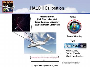
HALO II Calibration
Presented at the Utah State University / Space
Dynamics Laboratory 2001 Calibration Conference
Author
James Kiessling
with
James Allen, Dennis Hakala, Mark Lambrecht
Intensity
Time
The paper was approved for open publication on
5 October 2001 as OSD case number 01-5-4081.
Logan Utah, September 20, 2001
2
Presentation Outline
- HALO II Overview
- Calibration Requirements
- Operations Model
- Calibration Methodology
- Ground-Based Characterization
- In-Flight Calibration
- Summary
3
HALO-II Overview
Large Optic, Multiple Camera system designed to
address BMDO TE needs Installed on a Low cost
Gulfstream IIb platform Serve as prototype for
BMDO surveillance and battlefield support
developments
Heimdall-IR? Surveillance System
Aggressive 2-Year Start To Finish Program
3
4
Motivation For HALO IIMeet BMDO TE Requirements
Orbital Signatures
Exo-AtmosphericTarget Characterization
Chemical Releases
Counter- measureSignatures
Vehicle Separation
Plume Signatures
Target Signatures
Kill Assessment orMiss Distance
TrajectoryReconstruction
Booster Tracks
Failure Diagnostics
Photodocumentation
Flash Radiometry
FOR
Interceptor Performance
Sensor / Technology Testbed
4
5
Heimdall Sensor
Rotating Barrel
Heimdall is the watchman of Norse mythology. His
horse is Gulltop and his eyesight is so sharp
that he can see for hundreds of leagues in all
directions as plainly by night as day.
Heimdall is an integrated surveillance system
including an aerodynamic pod, highly stable
optics, infrared and visible staring sensors,
high performance computers and very fast data
storage. It is adaptable to manned and unmanned
aircraft for side-looking and up-looking
surveillance of ballistic missiles in all phases
of flight.
6
HALO II Design ImplementationSystem Layout
Aerodynamic Pod Contents HALO Upgrade Pointing,
Acquisition, and Tracking Subsystems
Forward Cabin HALO Legacy Sensors Guest Sensor
Platforms
Aft Cabin HALO Upgrade Real Time Processor and
Surveillance Processor Systems
7
Pointing Subsystemand Pod Design
Pod is sealed purged at all times except during
high altitude operations
Environmental Control System
- Active stabilization
- 35 cm Ritchey-Chretien telescope
- Few optical surfaces minimizes transmission
losses - Contamination / Environment Control
Aft Section
Rotating Barrel Section
Barrel Drive
Under Barrel Section
Acq. Subsystem
Primary Mirror
Open Port
Forward Section
Secondary Mirror
Tracking Subsystem
Porous Fence
Below Horizon to Zenith to Below horizon
Steering Mirror
Paddle Torquer
Roll Gimbal
Fiber Optic Gyro
8
Acquisition SubsystemOptical Path and Subsystem
Overview
Acquisition Subsystem
Optical Path
Secondary Mirror
- 2.5 degree field of view
- Integrated COTS cameras
- 6-position filter wheels for all cameras
- 2 MWIR cameras - 30 Hz frame rate
- 256x256 InSb
- 2 to 5.5 mm response
- NEFD
- Closed cycle coolers
- Visible - 1024 x 1024 CCD
- Fiber-optic digital interfaces
- Digital data (all sensors)
- Digital command control
- Gain, frame rate, integration time
- Filter wheel control, NUC
- On-board calibration sources
- Hot / cold flood sources
9
Tracking SubsystemOptical Path and Subsystem
Overview
Optical Path
Tracking Subsystem
- 0.25 degree field of view
- Common/custom dewar for MWIR/LWIR
- Closed cycle coolers
- 6 position cold filter wheels for all sensors
- LWIR 30 Hz frame rate
- 256 x 256 HgCdTe SC 117 SCA
- 5.7 to 13 µm, NEFD
- MWIR 30 Hz frame rate
- 256x256 InSb AE 194 SCA
- 1.2 to 5.5 µm, NEFD
- Visible 1024 x 1024 CCD
- Fiber-optic digital interfaces
- Digital data (all sensors)
- Gain, frame rate, integration time
- Filter wheel control, NUC
- On-board calibration source
- Hot/cold flood source
10
Calibration Requirements
- All HALO II cameras are required to provide
better than 20 absolute radiometric calibration - Goal of better than 10
- MWIR Acquisition cameras within 2.0 µm to 5.0 µm.
band-pass - MWIR Tracking camera within 2.5 µm to 5.0 µm.
band-pass - LWIR Tracking camera within 8 µm to 12 µm.
band-pass - Based on Celestial Standards using In-flight
values - HALO II Pointing Subsystem is required to provide
knowledge of sensor bore-sight to 5 µRadian - Stressing pointing alignment
- ECI Frame Alignment, celestial reference
- HALO II Radiometric Error Budget
- Cal RSS( Source Error, Atmospheric
Transmission Error, Spectral Response Error,
Measurement Error, Model Error, PSF correction
Error) - HALO II Pointing Knowledge Error Budget
- PK (uR) RSS( ephemeris error, star centroiding
error, refraction error, jitter, time dependent
drift)
11
Sensor Operation Model Differential Radiometry
via Dithered Operations
Time Dependent Process
Incoming Photons
Compute Statistics , sigma Apply NUC
include pedestal
Blob Association (Raster Process) Type and Kill
Blobs
Bkg Level, Noise Est.
LOS Dither
Optics
NUC Tables
Point / Extended
Detector Arrays
Type dependant Centroiding and radiometric
Estimate (RON)
Dead Pixel Maps
Bkg Estimate 96 (last 64) rotary buffer
Raw Data
Exceedance List (array)
Bkg Subtraction Exceedance Detection
External Motion Vector
Single Frame Object List
RAID Array (Raw Data)
Frame to frame association and Angles only tracker
Image Stabilization Anti Dither Display
RAID Array (Processed)
ECI State Tracker / Target Recognition
Display
MPR (Future)
12
Calibration Basis
- Ground Characterization Measurements
- Spectral response measurement per filter
- PSF off pixel center response correction
- In-Flight Calibration of system follows identical
process as data collection - Flat-Fielding / Non-uniformity determination
using hot and cold flood sources - Apply calculated bias and slope values for each
pixel - Background estimation and removal using dither
against open port dark-sky - Dithered star measurements, centroid compensated
using PSF correction table - Statistic of corrected (absorption and centroid)
star amplitude above background - Compute system response via curve fit to star
amplitudes and corrected fluence levels - Hundreds of frames, statistically balanced vice
SNR
Notional Spectral response
Notional PSF Correction
13
Thermal Flood Source
Thermal Flood Source design 15 inch diameter
insulated foil heater 7 Temperature sensors
around the heater assembly
- Thermal Flood Source will permit in-flight, N
point Non-Uniformity Correction (NUC) by rotating
the mirror with barrel closed to view the thermal
source. - Thermal Flood Source requirements
- Temperature easily controlled and monitored by
operator - Temperature uniformity across surface
- Acceptable weight, size, and power
- Large size (overfill aperture)
- Environmental Tolerance
- High emissivity
- Secure mounting
Aluminum heat sink bonded to top of
heater Fiberglass tray bonded to bottom of
heater Tray bolts under barrel contoured as shown
14
Background Estimation
Raw Image
Processed Image
- Exploit Dither Pattern (Known Object Location) to
Estimate Background. - Time-Delayed - Average of Frames from 1 to 3
Seconds Prior to Current Frame (Blue Region) - Good BG in Current Target Location
- Improved SNR
15
Centroiding Unresolved Targets
- Rule of Nines
- 3 X 3 Array Centered on Object
- Horizontal and Vertical Peak-to-Wing Ratios
- Horizontal Ratios Generate Family of Curves for
Vertical Ratios - Laboratory Measurements for Each Sensor
- Validated with Mathematical Model
- Airy Disk Input
- To be measured in detail in ground testing
- Generate look-up tables for real-time processing
- Simulation predicts peak target SNR of 20
16
Source Error
- Stellar Models / Data Base
- Models used will be based upon Cohen and Walker
spectral templates for non-variable stars - Updated as needed to include recent developments
- Used in the BMD measurement community
- Magnitude of errors 2 (Vega MWIR) to 5 in
LWIR - Stellar Databases will include both astrometric
and radiometric references - Hipparcos/Tycho database will be used for visible
/ IR stars for pointing calibrations (0.7 µR
error) - Pointing measurements will be used for alignment
of the platforms and for gathering data for
atmospheric refraction calculations - Stellar Measurements
- AFRL led effort to update community models with
new data
17
Atmospheric Effects
Absorption / Source Correction Atmosphere model
(MODTRAN) updated with flight data, absorption
calculated as a function of the pointing angle
and pressure height. Atmospheric
Refraction Atmospheric refraction calculated to
first order from pressure height, Standard
Atmosphere Tables and elevation angle,
differential correction applied from measured
difference between visible and IR elevation to
star (dispersion effect) Ref. The Explanatory
Supplement to the Astronomical Almanac
(Visible) Ref. J. Saastamoinen gives correction
tables for other wavelengths and altitudes in
Introduction to Practical Computation of
Astronomical Refraction.
Wavelength (Microns)
Estimated Transmission error pointing errors 18
Radiometric Calibration Summary
HALO II Radiometric Error Budget Cal RSS(
Source Error, Atmospheric Transmission Error,
Spectral Response Error, Measurement Error, Model
Error, PSF correction Error) Source Error 2-5
depending on star (variability and wave
band) Atmospheric Transmission Error 1-3 (to
be determined using real-time updates to
MODTRAN) Spectral Response Error determined using Monochrometer measurements of
system) Measurement Error measurements degrading centriod accuracy,
backgrounds effects) Model Error fit to system response by star irradiance
measurements (curve fit error) ) PSF Correction
Factor correction to relative response from object blur
off-center from the peak pixel) Initial Root
Sum Square Error Expectation 9 to 9.5
Radiometric Calibration Accuracy of Data (We plan
to prioritize the reduction of the largest error
sources to improve this value)
19
Goniometric Calibration Summary
HALO II Pointing Knowledge Error Budget PK (uR)
RSS( ephemeris error, star centroiding error,
refraction error, jitter, time dependent
drift) Ephemeris Error 0.7 µR (Hubble Guide
Star catalog and Hipparcos / Tycho database)
Star Centroiding Error 1.4 µR (based on SNR
of 20 for visible object) Atmospheric Refraction
Error 2 µR (to be determined using flight
data) Residual Jitter Error 1/10 G vibration input, revise on measurements of
system) Time Dependant Gyro Drift (Maximum allowable drift rate of Gyros, revise on
measurements) Initial Root Sum Square Error
Expectation 3 µR at celestial calibration to 5
µR six minutes later (We plan to collect data on
incidental star crossings in the FOV to
continuously re-align )
20
Conclusion
- Key Attributes
- Multi-camera, Multi-spectral system
- Exceptional sensitivity
- Very large field of regard
- Precision real-time radiometry
- Real-time Ballistic track generation
- Flexible configuration/Filter selectivity
- Other Attributes
- High altitude collections
- Minimal ground support
- Accommodates guest sensors
- Very low development cost
- Modest annual OM cost
- HALO II is designed to meet BMDOs key data
collection requirements
The author would like to acknowledge the fine
work and administration of the HALO II program
provided by Mr. Mike Lash and the SMDC Technical
Center Staff.
21
Backups
22
HALO II Points of Contact
- U.S. Army Space Missile Defense Command
- Mr. Mike Lash, HALO Program Manager, SMDC-TC-SP
- Mr. Ken Strom, HALO II Integrator, SMDC-TC-SP
- Ballistic Missile Defense Organization
- Mr. Larry Wingfield, Program Manager
- Mr. Jim Kiessling, Chief Engineer
- Aeromet, Inc., Tulsa, OK
- Mr. Rob Moskal, Program Manager
- Mr. Garry Booker, Chief Engineer
23
HALO II Design Requirements
- Meet BMDO electro-optical requirements for
ballistic missile Test Evaluation (TE) - Required
- High quality photo-documentation
- Characterization of target scene suitable for
diagnostic evaluation of event - Metric characterization of the system(s)
- Radiometric characterization of the system(s)
- Collection of phenomenology and signatures
- Desired
- Real-time track development
- Target-object mapping (TOM)
- Real-time discrimination of threat objects for
target complex - View and collection of non-missile targets
24
HALO II Subsystem Performance
Recommended
CrystalGraphics Presentations


