
Definition of Nasmyth focal plane from Ryujisan - PowerPoint PPT Presentation
1 / 6
Title:
Definition of Nasmyth focal plane from Ryujisan
Description:
They put a piece of paper with cross lines on the mechanically defined focal ... 2 screws per stop will provide adequate clamping force to secure these stops ... – PowerPoint PPT presentation
Number of Views:43
Avg rating:3.0/5.0
Title: Definition of Nasmyth focal plane from Ryujisan
1
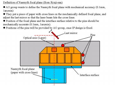
Definition of Nasmyth focal plane (from Ryuji-san)
- AO group wants to define the Nasmyth focal plane
with mechanical accuracy (0.1mm, 1arcmin) - They put a piece of paper with cross lines on
the mechanically defined focal plane, and adjust
the last mirror so that the laser beam hits the
cross lines. - Position of the focal plane and the interface
surface relative to the pins should be
mechanically accurate (0.1mm, 1arcmin). - Positions of the pins will be provided by AO
group, once IP design is fixed.
Last mirror
Pins
Optical axis (Laser)
Nasmyth focal plane (paper with cross lines)
Interface surface
2
Proposed Design for IP Alignment to AO
Bench The proposed alignment design uses the
same edges for the stops as shown in a PowerPoint
send by Ryuji (see first slide), but the longer
side is used with the 2 stops rather than the
short side. This will improve the accuracy of the
alignment. Because the stops have a low profile
(12.7 mm), they probably can be located the way
it is shown in this PowerPoint document and will
clear any hardware that is nearby. If it doesnt
clear, then the stops can be moved over in
increments of 25 mm, since this is the hole
pattern spacing of the AO Bench Surface The stops
will be located via the hole pattern on the AO
Bench Surface. We will know the theoretical gap
between stop and IP Plate for the 3 stops.
Initially Installment Gap Spacers will be used
between these stops and the IP Plate. This will
probably locate the IP Plate already to the
required precision of 0.1 mm and 1 arcmin. The
Installment Gap Spacers will then be removed and
the stop screws will be advanced to touch the IP
Plate. Note also that if a fine adjustment is
needed, these screws can be used for that
purpose. I feel that 2 screws per stop will
provide adequate clamping force to secure these
stops in place when installing the IP Plate it
will have to be done very carefully anyway.
3
(No Transcript)
4
(No Transcript)
5
(No Transcript)
6
Installment Gap Spacer will fit in here
Recommended
CrystalGraphics Presentations


