
GEM UNIT Autonomous GEM Vehicle - PowerPoint PPT Presentation
1 / 28
Title: GEM UNIT Autonomous GEM Vehicle
1
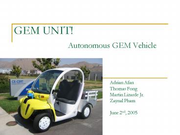
GEM UNIT! Autonomous GEM Vehicle
- Adrian Afan
- Thomas Fong
- Martin Lizarde Jr.
- Zaynal Pham
- June 2nd, 2005
2
Introduction
- Objective
- to modify a neighborhood electric vehicle (GEM)
to autonomously move from one location to another
while detecting and avoiding objects along the
way - the GEM can be manually controlled via a joystick
in a drive-by-wire configuration - when the desired location is reached, the GEM
will park itself in a designated parking spot
3
Introduction (Continued)
- Approach
- the GEM is guided using x and y mapping via
Global Positioning System (GPS) and uses a laser
range finder to detect and avoid obstacles - parking will be implemented by utilizing a
specifically designed object that the vehicle
will detect and use as a reference point to align
and park directly in front of - The joystick is interfaced to a microcontroller
to control the vehicle manually
4
Introduction (Continued)
- The microcontroller will be used to control the
throttle, braking, steering based on the input
from the joystick - The master controller (laptop) will be used for
more demanding applications and processing such
as communication with the GPS, laser range
finder, digital compass - It processes the data to find the desired heading
of the vehicle toward the destination point and
the path needed to avoid any obstacles on the way
5
Technical Approach
6
Circuit Schematic
7
Microcontroller Algorithm
- Acceleration
- Reacts Linearly to the Joystick Input
- Joystick increases acceleration when pushed
forward - Speed range is 0 to 15mph
- Braking
- Joystick increases braking when pulled backward
- Can stop vehicle slowly or almost instantaneously
8
Microcontroller Algorithm - Turning
- Turning
- Joystick is used as input, steering encoder used
as feedback - Both cover range from 0 to 5V, left to right
- Voltages are compared for turning
- If encoder has smaller voltage, wheels are
signaled to turn right - If encoder has larger voltage, wheels are
signaled to turn left
9
Microcontroller Algorithm - Communication
- Serial Communication
- If data is detected on the serial port and the
joystick is in the neutral position, the vehicle
will run autonomously - Serial data is ignored if the joystick is outside
of the neutral position - ASCII value determine the actions of the GEM
- Serial data need to be sent in pairs
- Serial timeout present to prevent microcontroller
from freezing while waiting for message
10
Autonomous Algorithm
- System designed to home in on final point
- Vehicle will go a constant speed unless no paths
are detected or it has reached the final
destination - Algorithm
- If ( vehicle is close to the desired location)
- Tell the vehicle that it has reached the final
destination and stop the vehicle
11
Autonomous Algorithm - Continued
- If ( Destination is almost directly North or
South of vehicle) - Assign a predefined desired angle
- Else
- Convert the GPS coordinate system into a regular
XY coordinate system - Then the desired angle is calculated using
12
Autonomous Algorithm - Continued
- Desired angle is converted into the regular
coordinate system - Heading angle is converted into the regular
coordinate system - The difference in the desired angle and the
heading angle is determined - From this difference, the bias path is returned
to the obstacle avoidance algorithm - There are 5 predetermined paths the vehicle can
take. - The bias path is the path toward the destination
without accounting for obstacles
13
Obstacle Avoidance Algorithm
14
Testing Plan
- Demonstrate manual GEM control via joystick
- Tweak microcontroller code for functionality and
ride smoothness - Ensure complete safety of system through testing
of responsiveness as well as emergency cut-off
and stopping procedures.
15
Testing Plan - Continued
- Demonstrate the GEM moving from one location to
another at the CE-CERT parking lot while
detecting and avoiding objects - Create obstacle map while under manual control
- Find current GPS location and path to desired
location while under manual control - Allow vehicle to navigate autonomously to desired
location via GPS without obstacles.
16
Testing Plan - Continued
- Integrate obstacle map with path planning
algorithm and find paths around obstacles to
desired location while under manual control. - Full autonomous movement to desired location with
obstacle detection and avoidance - Input multiple destination points into program.
Vehicle should drive to each point, stop
momentarily and continue to the next point
17
Results
- Mechanical Implementation Successful
- Braking, Throttle and Steering respond correctly
to joystick inputs - Steering Motor Mount does not flex while in use.
Chain and sprocket are very durable and have no
slack to add to the steering delay - Emergency Brakes have been tweaked to stop the
vehicle as fast as possible
18
Results - Continued
- PC Communication with sensors and microcontroller
work well - Laser range finder updates the obstacle map at 1
Hz - GPS and Compass values are updated whenever the
laser range finder updates - Vehicle runs autonomously with little difficulty
- Vehicle detects obstacles and can maneuver around
them to follow a clear path - Vehicle stops upon nearing the destination
19
Results - Continued
- Minor Issues
- Brake controller has a threshold voltage before
it activates the brakes. - The joystick needs to be pulled back about a
third of the way - Causes the braking to be very sudden
- The steering is slow
- Takes about 2-3 seconds to get from one side to
the other - Laser Range Finder can only detect objects higher
than 3 feet tall - Can be blinded by bright sunlight at the right
angle
20
Future Work
- Improvements to Design
- Implement Reverse and other car controls into
Microcontroller - Add ability for microcontroller to control
direction - Allows vehicle to back out of traps
- Buttons on Joystick can be mapped to horn,
changing vehicle direction, or signaling - Add more safety features
- Throttle cutoff if power to DAC circuit is lost
- Component Cutoff switches near driver
- Toggle brake lights when car is stopping
21
Future Work - Continued
- Parking
- Identify special obstacle and park in front of it
- Update Faster
- Stabilize the code for updating the obstacle map
at 5Hz - Creation of PCB for DAC circuit
- PCB has already been designed
- Need to fix pin assignments
- Improved Path Planning and Obstacle
Identification Algorithms
22
Future Work - Continued
- Application for Future
- Identify an obstacle and follow it
- Expansion to larger vehicle and system to compete
in DARPA Grand Challenge - Next Slide Video
- Focus on the two stationary GEM vehicles
- Notice how it avoids the first one by turning
right and then avoids the second one by turning
left - After the vehicle passes the obstacles, it
realigns with the destination point and heads
towards it - Vehicle stops very close to the desired
destination point marked by the cone
23
Video
24
Pictures
- (From Left to Right) Martin Lizarde, Thomas Fong,
Adrian Afan, Zaynal Pham - Special Thanks to Dr. Barth, Dr. Beni and all the
people who helped us with this project!
G-g-G-gem unit
25
Appendix A - Budget
26
Appendix B - Cost Analysis/Alternate Solutions
- Electro-Hydraulic Brake Controller
- While it stops the vehicle very well, it is not
smooth as originally assumed to be - Possibly because a dedicated brake controller
with an internal accelerometer was not purchased
with the system - Could be replaced by a linear motor operating the
master cylinder - This would be smoother, but would need feedback
to get proper braking
27
Appendix B - Cost Analysis/Alternate Solutions
Continued
- SICK Laser Scanner
- Provides a very accurate map of surroundings that
it can see - Does not see small objects that fall underneath
its field of vision - Needs to be supplemented by ultrasonic sensors
- Cannot be replaced by ultrasonic sensors because
they lack the range given by the laser scanner - Can be replaced by computer vision
- Faster computer would be needed with good
obstacle detection algorithms
28
Appendix B - Cost Analysis / Alternate Solutions
- Continued
- Steering Motor
- Faster Motor with Similar Torque
- This would increase responsiveness of steering
- Small amount of space available around mounting
point - Could be replaced with Linear Motor
- Would need to be very strong to move tires
- Novel mechanical mechanism could multiply force
exerted on tires and ensure that the physical
limits of steering mechanism are not violated
Recommended
CrystalGraphics Presentations


