Adaptive secondary mirrors for LBT - PowerPoint PPT Presentation
1 / 28
Title:
Adaptive secondary mirrors for LBT
Description:
... f 3333f3 33 3333333f33 3333 3f3f33ff3f 3f3f 3 3 33 f3 3 3 3333f3 33 3 3 33 ... ff f f 3f ff f f ff3fff ff f f 3f ff f f 3 f 3 33 3f 3 3 3 ... – PowerPoint PPT presentation
Number of Views:63
Avg rating:3.0/5.0
Title: Adaptive secondary mirrors for LBT
1
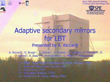
Adaptive secondary mirrors for LBT
Spy's 48th Annual Meeting3-8 Aug 2003 San Diego,
CA, USA
Presented by A. Riccardi
A. Riccardi1, G. Brusa1,2, P. Salinari1 , S.
Busoni1, O. Lardiere1, P. Ranfagni1, D.
Gallieni3, R. Biasi4, M. Andrighettoni4, S.
Miller2, P. Mantegazza5
1 INAF - Osservatorio Astrofisico di Arcetri,
Firenze, ITALY 2 Steward Observatory, Tucson,
USA 3 ADS, Lecco, ITALY 4 Microgate, Bolzano,
ITALY 5 Politecnico di Milano, Milano, ITALY
2
Overview
- LBT AS units layout
- New features wrt MMT AS and tests on P45
- New cabling and capsens noise
- Effectiveness of new control strategy
- Optical quality of the new thin shell
- Optical test facility in Arcetri
- Schedule
- Conclusions
3
Partners
INAF-Osservatorio Astrofisico di Arcetri
(Italy) Conceptual design. Optical and
electromech tests, calibration and diagnostic
software development.
ADS (Italy) mechanical engineering,mechanical
drawings, production and assembly
Microgate (Italy) electronics development
and production. DSP software development.
Mirror Lab-Steward Observatory (USA) Optical
components production (aspheric shells and
reference plates)
4
Adaptive secondary in LBT
2x8.4m mirrors
5
LBT672 layout
6
From MMT336 to LBT672
The LBT672 design is based on the experience
gained during the extensive tests in lab and at
the telescope of MMT336.
Both mechanics and electronics has been revised
improving performances, stability, reliability,
maintenance with respect to MMT336.
7
P45 prototype
First 3 internal rings offinal LBT672 unit
240mm
8
New LBT technological solutions
9
New LBT technological solutions
10
New LBT technological solutions
11
New LBT technological solutions
12
P45 capsens noise
Typical 1.7nm rms Max 2.5 nm rms Only 6 of 45
acts (13) have noise gt 1.8nm rms
This validates new capsensor and cabling
solutions
13
New Control Electronic/Comm.
Total computational power 78 Gmac/s (32bit
fp) Real-time reconstructor on-boardWFS 30x30
gt 34-47ms (z-m) Slope comm time 20ms
Communication Board
Communication Board
Communication Board
Communication Board
Communication Board
Communication Board
(1x backplane)
(1x backplane)
(1x backplane)
(1x backplane)
(1x backplane)
(1x backplane)
Reference Signal
Reference Signal
Reference Signal
Reference Signal
Reference Signal
Reference Signal
Generator Board (1x backplane)
Generator Board (1x backplane)
Generator Board (1x backplane)
Generator Board (1x backplane)
Generator Board (1x backplane)
Generator Board (1x backplane)
DSP control Board (14x backplane)
48V, 35 A
Power
DSP control Board (14x backplane)
DSP control Board (14x backplane)
DSP control Board (14x backplane)
DSP control Board (14x backplane)
DSP control Board (14x backplane)
DSP control Board (14x backplane)
DSP control Board (14x backplane)
Liquid cooled crates,
each comprehending 2 backplanes (3x)
3 cooled electronics boxes2 crates/box 84 custom
DSP boards 2 DSP/board - 8 acts/board 32-bit
floating-point 470Mmac/s (MMT 16-bit integer
40Mmac/s)
Distribution boards
Actuators
Coil
Gap
Thin mirror
Reference signal
14
New control implementation
DCommand vectorfrom rec.
Feed-forward force
56kHz_at_-3dB
?FikDck
?
12.5ms
40kHz
CurrentDriverand coil
Dci(t)
G
Delay
DAC
?
-
-
e(t)
p(t)
MirrorShell
ADC
LIN
CapacitiveSensor
Control loop of i-th actuator
27kHz_at_-3dB
40kHzeffective
n(t)
MMT air trapped in the 50mm gap provides viscous
damping it limits the effective
positioning range at 25-30mm
15
PV control test with P45
Digital damping
Gap67mm Gprop 0.1N/mm Gderiv 25Ns/m
Dnatural 17Ns/m
16
P45 thin shell flattening
17
P45 thin shell flattening
253 Zernike polynomials fitting
14nm rms (surface) (lt50 of any flattening of MMT
and its protos)Max flattening force 45 of the
weight per actuator (65mN) (30) Rms flattening
force 18 of the weight per actuator Gives only
3 increment of power wrt power for weight support
This validates the new Mirror Lab procedure to
produce shells
18
Optical test tower in Arcetri
- 15m tower
- Thermalized optical path
- Test AdSecAO module in closed loop (see
5169-17 EspositoTozzi) - Test calibration procedures
19
Schedule
- Sep 2003 start of LBT672a/b mechanics production
- Oct 2003 new DSP board on P45
- Nov 2003 LBT672a reference plate ready
- Nov 2003 start of LBT672a/b electronics
production - Jan 2004 LBT672a thin shell ready
- Mar 2004 LBT672b optics ready
- Jun 2004 LBT672a ready at Arcetri for
charcterization and tests with
First Light AO module. - Sep 2004 LBT672a delivery to LBT site for 1st
light - Spring 2005 LBT672b delivery to LBT site
20
Conclusions
- Both mechanics and electronics has been revised
improving performances, stability, reliability,
maintenance with respect to MMT336. - Most of the new features have been successfully
tested with P45. New actuators, cabling,
distribution boards, capacitive sensor boards,
reference plate coating, electronic damping and
thin shell optical quality. - New LBT DSP boards will be ready on next October
for testing on P45 - The optical test facility in Arcetri for AS
calibration and test of CL operations with the
1st light AO module under construction (Sep
2003).
21
The End
22
Performances
23
New capacitive sensor
DSP board
ADC
80kHz
80ksamp/s
40kHz
Pos at 40kHz
MMT case
24
(No Transcript)
25
(No Transcript)
26
LBT CapSens tested on P1 prototype
90kHz_at_-3dB
27
MMT cabling
MMT actuator andits cable as one unit
28
New cabling test


