Muon detection in NA60 - PowerPoint PPT Presentation
1 / 24
Title:
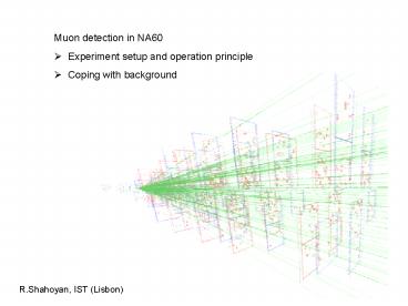
Muon detection in NA60
Description:
muon spectrometer. NA60 setup and ... the muon measured in the spectrometer ... muon spectrometer. Matching is done by selecting muon - VT track associations ... – PowerPoint PPT presentation
Number of Views:38
Avg rating:3.0/5.0
Title: Muon detection in NA60
1
- Muon detection in NA60
- Experiment setup and operation principle
- Coping with background
R.Shahoyan, IST (Lisbon)
2
NA60 setup and operation principle
Concept of NA60 place a silicon tracking
telescope in the vertex region to measure the
muons before they suffer multiple scattering in
the absorberand match them to the muon measured
in the spectrometer ?Improved kinematics
(20 MeV/c2 at ? instead of 80 MeV/c2 in
NA50)Origin of muons can be accurately determined
3
NA60 setup and operation principle
40 cm BeO 25 cm Al2O3 440 cm C 40 cm Fe?50
X0 and 14 ??I Together with 120 cm Iron wall
imposes 4.5 GeV cut on triggered mouns
7 Indium subtargets with 8 mm spacingl 1.5mm, Ø
1mm, except the first one with Ø 12mm?0.16
In-In interaction probability
Note muons suffer most of the multiple
scattering in the end of the absorber ? allows
partially to correct the measured angles (Branson
plane correction).
4
NA60 setup and operation principle
8 MWPC (24 planes) with 2mm pitch 4 scintillator
trigger hodoscopes ?highly selective dimuon
trigger4.5?107 ion per 6s burst (1.2 MHz
int.rate)? 5000 triggers? 50 lead to
reconstructed dimuon
5
Dimuon trigger
- Azimuthal acceptance is split to 6 windows of 42o
(because of the magnet coils) - Trigger requires at least 2 sextants with single
muon condition - similar slabs are fired in 2 homothetic
hodoscopes (R1,R2) before the magnet (selects
the particles coming from the target region,
measures polar angle) - fired slabs in 2 hodoscopes (R3,R4) after the
magnet are allowed by the special r1,2r3r4
slabs coincidences matrix accounting for the
deflection (1/PT) of the muon with acceptable
momentum in the toroidal magnetic field (rough
momentum measurement) - Trigger efficiency (90) is monitored by extra
hodoscopes during special runs
6
NA60 setup and operation principle
Beam Trackermeausers incoming ion with ?x,y20?m
pixel (ALICE1) planes ( 2X0 per plane)
7
NA60 setup and operation principle
VT tracks ?p/p 6 ?? ? 1 mrad?impact 50 ?m
measured muons ?p/p 2 ?? 10 mradimpact
5 cm (at 10 GeV/c)
Matching is done by selecting muon - VT track
associations with small enough weighted distance
(?2matching) in x,y-slopes and inverse momentum.
8
Effect of the matching on the mass resolution
Mass spectrum from the Muon Spectrometer
only(?M 80 MeV/c2 at ??)
Dimuon matching rate 70 at J/?,decreases
towards low masses(difference between the
detector acceptances, VT reconstruction eff
Mass spectrum after matching(?M 20 MeV/c2 at ??)
9
Matching between muons and tracks in vertex
region
- Each muon may be associated with VT tracks made
of clusters generated by - correct muon only (or its parent for ??,K???)
correct match - completely alien tracks fake match
- correct muon and some extra clusters from other
tracks if the track is present only because
the muon left enough hits correct if the
track would exist even in the absence of the muon
hits fake - The dimuon is correctly matched if none of the
2 muons is fake
10
Matching between muons and tracks in vertex
region
By varying the cut on the matching ?2 we can
change the signal / fakes ratio Since the muons
from ?,K decays have typically higher matching ?2
than the prompt ones (due to decay angle between
the parent in VT and muon in the MS ), we can
reduce the combinatorial background contribution
by tightening the matching condition.
11
Acceptance for matched dimuons (enhanced at low
M/Pt wrt NA50 thanks to the dipole magnet )
12
Vertex resolution (along the beam axis)
Good target identification even for the most
peripheral collisions (? 4 tracks) The
interaction vertex is identified with better than
200 mm accuracy along the beam axis
13
Vertex resolution (in the transverse plane)
Beam Tracker measurement vs. vertex reconstructed
with Vertex Tracker
The BT measurement (with 20 ?m resolution at the
target) allows us to control the vertexing
resolution and systematics
The interaction vertex is identified witha
resolution of 1020 mm accuracy in the transverse
plane
14
Offset resolution (and its dependence on
alignment)
J/? at SPS energies is always prompt use it to
monitor the offset resolutionFor real analysis
use offsets weighted by the track and vertex fir
error matrix, to minimize the dependence of the
cuts on the muon momentum
Data presentedat QM05
After fine alignment (2006)
15
Background Subtraction
16
Background Subtraction
Combinatorial Background (mainly from
uncorrelated ? and K decays)Subtracted by
building a sample of ?? pairs using muons from
different Like Sign events.Mixing procedure
accounts for correlations in the data due to the
dimuon trigger.
17
Background Subtraction
Subtracting the Mixed CB from the data we obtain
the Signal (correct and fake) in ??- sample and
zero (or residual background) in the Like Sign
dimuons sample.
18
Background Subtraction
The Fake Matches Background is subtracted by
Monte Carlo (used for the Low Mass Analysis) or
by matching the muons from one event to tracks
from another one a special weighting procedure
is used to account for the mixed fake matches
19
Background Subtraction
20
Background Subtraction
21
Background Subtraction
22
Background Subtraction
Comb.bckg. generation quality is monitored by
comparison to Like-Sign spectra.
Fake matches bckg. generation quality is
monitored by comparison to MC overlaid by real
data
23
Background Subtraction (offsets)
The mixed background sample (fake matches and
combinatorial) must reproduce the offsets of the
measured events therefore, the offsets of the
single muons (from different events) selected for
mixing must be replicated in the mixed event.
(All masses)
24
Final spectra
Data integrated over centrality(with old
alignment!) Matching ?2 lt 1.5


