Ball on Beam Balancer System - PowerPoint PPT Presentation
1 / 19
Title:
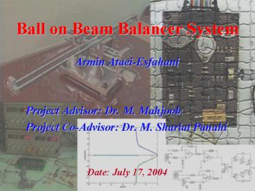
Ball on Beam Balancer System
Description:
The voltage of motor mounted potentiometer is constantly compared with the desired voltage. ... Linear Potentiometer Circuit. Electronic Board Features. On/Off Switch. ... – PowerPoint PPT presentation
Number of Views:1058
Avg rating:3.0/5.0
Title: Ball on Beam Balancer System
1
Ball on Beam Balancer System
- Armin Ataei-Esfahani
- Project Advisor Dr. M. Mahjoob
- Project Co-Advisor Dr. M. Shariat Panahi
Date July 17, 2004
2
Introduction
- The ball on beam balancer system is one of the
most enduringly popular and important laboratory
models for teaching control systems engineering. - Control Job Automatically regulating the
position of the ball on the beam by changing the
angle of the beam. - The open loop is unstable.
3
Practical Examples of Unstable Systems
- In chemical process industries the control of
exothermic chemical reactions. - In power generation the position control of the
plasma in the Joint European Tours (JET). - In aerospace the control of a rocket or aircraft
during vertical take-off.
4
Apparatus Design and Construction
- Base and Leveling Screws
- Motor Pod and Bushes
- Back Pod and Bushes
- Shaft and Shaft Bushes
- Bearing Covers
- Rotating Base
- Runner
5
System Modeling
- Ball on Beam Balancer Modeling
- DC Motor Modeling
- Theory
- Experiment
6
Ball on Beam Balancer Modeling
7
DC Motor Modeling
- The actuator in this system is a DC motor,
M(s) that is coupled through gearing to the beam
shaft. The DC motor will be controlled with a
local feedback loop in which beam angular
position is measured with the shaft-mounted
potentiometer (Kp).
8
DC Motor Modeling - Circuits
- The voltage of motor mounted potentiometer is
constantly compared with the desired voltage. - A 1.6 volt is added to the output voltage to
eliminate the motor dead zone.
9
DC Motor Modeling Curve Fitting
- We fit the equation of the step response of a
second order system (c (t)) to the plot gained
from the experiment, to get the parameters that
give the closest possible curve. - The settling time is taken equal to the time
during which the response reaches 80 of the step
value. Applying Root Mean Squares rule (RMS) we
composed an M-File checking different values of ?
in a "For Loop", and found ? and ? which give
best-fitted curve.
10
Experiment Data and the Fitted Curve
Best Fitted Curve Parameters ? 1.0601, ?
0.5168
11
System Simulation and Controller Design
Open Loop System
12
Effects of Adding Zeros
Effect of Adding One Zero
Effect of Adding Two Zeros
13
Designed PD Controller
14
Controller Implementation
- Sensing angular and linear positions. A.
Setting A/D card parameter B. Running data
acquisition procedures. - Performing controller computations.
- Sending computed voltage to the circuit through
an D/A card. A. Setting D/A parameters. B.
Setting reference voltage.
15
Controller Implementation - Notes
- Saturation Problem.
- Linearity of Sensors.
- Motor Dead Zone.
- Non-linearity in Motor Dead Zone.
- Motor Driver Voltage Consumption.
16
Motor Driver Circuit
17
Angular Sensor Circuit
18
Linear Potentiometer Circuit
19
Electronic Board Features
- On/Off Switch.
- Three mode switch that enables the user to choose
from three modes a. using the built in
circuits. b. controlling the system manually
c. using an analog controller


