Polarimetry at the ILC
1 / 12
Title:
Polarimetry at the ILC
Description:
... Polarimeter 2001-01-26 V.Gharibyan, N.Meyners, P.Schuler. STUDIES FOR A DOWNSTREAM COMPTON POLARIMETER ... Upstream polarimeter needs to be before energy slit. ... –
Number of Views:66
Avg rating:3.0/5.0
Title: Polarimetry at the ILC
1
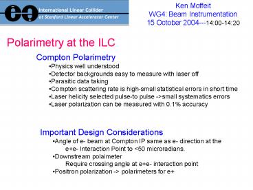
Polarimetry at the ILC
Ken Moffeit WG4 Beam Instrumentation 15 October
2004---1400-1420
- Compton Polarimetry
- Physics well understood
- Detector backgrounds easy to measure with laser
off - Parasitic data taking
- Compton scattering rate is high-small statistical
errors in short time - Laser helicity selected pulse-to pulse -gtsmall
systematics errors - Laser polarization can be measured with 0.1
accuracy
- Important Design Considerations
- Angle of e- beam at Compton IP same as e-
direction at the - ee- Interaction Point to lt50 microradians.
- Downstream polaimeter
- Require crossing angle at ee- interaction point
- Positron polarization -gt polarimeters for e
2
References
IPBI TN-2003-1 Status of Linear Collider Beam
Instrumentation Design, by D. Cinabro, E.
Torrence and M. Woods, May 2003. Also
available as an ALCPG Note LCD-ALCPG-03-0001
(2003).
IPBI TN-2003-2. Laser System for a Compton
Polarimeter, by K.C. Moffeit and M. Woods.
December 2003.
IPBI TN-2004-1. Luminosity, Energy and
Polarization Studies for the Linear Collider
Comparing ee- and e-e- for NLC and TESLA, by
M. Woods, A. Florimonte, K.C. Moffeit, T.O.
Raubenheimer, A. Seryi, and C. Sramek .
SLAC-PUB-10353. February 2004.
IPBI TN-2004-3. Spin Dynamics at the NLC, K.
Moffeit and M. Woods, June 2004.
STUDIES FOR A DOWNSTREAM COMPTON POLARIMETER AT
THE ILC.By M. Woods, K.C. Moffeit (SLAC),.
SLAC-PUB-10669, Aug 2004.
DET LC-DET-2001-047 The TESLA Compton
Polarimeter 2001-01-26 V.Gharibyan, N.Meyners,
P.Schuler
3
Layouts of the ILC
4
Location of Polarimeters
Having both an upstream and a downstream
polarimeter will assist in achieving Good
estimates of the systematic errors.
- Extraction-line beam diagnostics are highly
desirable at the ILC - More flexibility in the beam optics design than
upstream - Independent measurements with different
systematic errors - Allows improving systematic errors by sqrt (2)
- Directly measure beam-beam collision effects
- Compare measurements with and without collisions
- Probably requires crossing angle at ee-
interaction point
- Design Considerations
- Angle of e- beam at Compton IP is the same as the
e- direction at - the e e- IP (lt50 microradians).
- Upstream polarimeter needs to be before energy
slit. - Downstream polarimeter requires crossing angle at
- ee- interaction point
- Downstream polarimeter needs to be compatible
- with the energy spectrometer
5
Spin Precession
Change in spin direction for various bend angles
and the projection Of the longitudinal
polarization. Electron beam energy is 250 GeV.
6
Upstream Polarimeter
- Direction of beam at Compton IP is the same as at
the Detector IP (lt50mrad) - Laser beam access to Compton IP
- Measure laser polarization near Compton IP
- Measure Compton Scattered electrons
(backscattered 25 GeV) - momentum analyzed
- Detected with a segmented gas Cerenkov Counter
7
Layout of the Beam Delivery System to two
Interaction Regions with Crossing Angles
Should both IR-1 and IR-2 have locations For
upstream Compton Polarimeters? IR-1 has location
with direction okay IR-2 doesnt in plan above!
Upstream Polarimeter before energy slit
8
Extraction Line Beam Properties
Angular divergences of the incoming and disrupted
beams at the NLC IP BMT depolarization due to
the angular divergences.
9
Extraction Line Polarimeter Elements
Note Downstream polarimeter needs to be
compatible with the energy spectrometer
10
Summary of Depolarization Effects
Note The Table entries are for the NLC design.
Need to be redone for ILC design, in particular
the compressor and pre-Linac contribution.
11
Compton vs Luminosity weighted polarization
measurement
12
Summary
- Accelerator design issues
- Location of polarimeters
- Downstream polarimeter requires ee- crossing
angle - No net bend angle in e- beam direction at Compton
IP and e- direction at ee- IP - Positron polarization needs e polarimeters
- Polarimeter design issues
- Laser optics (20 hz high power al la SLC, every
bunch-TESLA design, resonate cavity--HERA) - Detectors
- Beam test needs before TDR
- Nothing stands out


