The Sivers Effect
1 / 17
Title: The Sivers Effect
1
The Sivers Effect
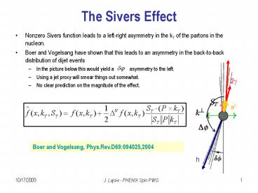
- Nonzero Sivers function leads to a left-right
asymmetry in the kT of the partons in the
nucleon. - Boer and Vogelsang have shown that this leads to
an asymmetry in the back-to-back distribution of
dijet events - In the picture below this would yield a
asymmetry to the left. - Using a jet proxy will smear things out somewhat.
- No clear prediction on the magnitude of the
effect.
Boer and Vogelsang, Phys.Rev.D69094025,2004
2
Asymmetry in Dijet Events
Boer and Vogelsang, PRD69094025,2004
anti-aligned
aligned
(plot shamelessly stolen from M. Chiu)
- The asymmetry leads to a shift in the away-side
peak of a two-particle correlation function,
depending on the jet orientation.
3
Radial Spin Component in Run-5
- We did have a nonzero radial component to the
polarization in Run-5.
From M. Togawa, 8/22/05 Spin PWG presentation.
WEST
EAST
4
Dataset
- Made use of LVL2 Photon filtered data
- LVL2 filtered events on EMC tower gt 3.5 GeV/c
- Fully efficient for p0s around 5 GeV/c
- Filtered during run and produced at ORNL using
pro.70 - Same good run list as ALL analysis
- Approx. 10 of runs not available as LVL2
filtered data - Event-by-Event spin data implemented as
recalibrator - Not yet in database, so calibration information
taken from disk files derived from Spin QA
histograms - Many thanks to Fukao for all his help!
5
Analysis Method (I)
Associated Charged
Trigger p0
Transverse component of blue () beam points into
EAST arm.
Transverse component of yellow () beam points
into WEST arm.
Correlation functions separated by spin
orientation and trigger arm.
6
Analysis Method (II)
- Define a set of correlation histograms based on
trigger arm, spin orientation - Define combinations of correlation function
histograms with the same trigger and spin
orientation for a given beam - Trigger same direction as blue spin, average over
yellow - Trigger opposite direction, average over yellow
7
Correlation Histograms (I)
- Correlation histograms constructed in 6cm vertex
bins, for each spin combination (,-,-,--) and
each trigger arm. - Mixed event background calculated for each
- Histograms summed over all runs, then acceptance
correction applied using mixed background - Acceptance correction normalized to 1 at near
angle peak - Corrected histograms summed over z-vertex and
normalized to the number of trigger particles
8
Correlation Histograms (II)
- Examples of typical correlations histograms
- BG (mixed event) and FG distributions
- bin at 0ltzlt6 cm, spin combination, west arm
trigger
FG same event pairs (acceptance corrected)
BG mixed event pairs (acceptance)
(note statistics in bg pairs)
9
Correlation Plot Averaging
In principle, each correlation plot should be
corrected and normalized in the same way. Plots
for the same trigger are and spin orientation
should be similar. This is a good first-order
crosscheck
Trigger along blue spin, average over yellow
NOTE Each correlation function normalized by the
number of trigger p0s.
10
Correlation Plots Yellow Averaged
- Gaussian fits to far-angle peak
Mean 3.122 /- 0.009 Sigma 0.423 /- 0.011
Mean 3.141 /- 0.009 Sigma 0.409 /- 0.018
Trigger p0 along transverse blue spin
Trigger p0 opposite transverse blue spin
11
Correlation Plots Blue Averaged
- Gaussian fits to far-angle peak
Mean 3.122 /- 0.009 Sigma 0.405 /- 0.010
Mean 3.141 /- 0.009 Sigma 0.429 /- 0.011
Trigger p0 along transverse yellow spin
Trigger p0 opposite transverse yellow spin
12
Asymmetries
- Just defined as difference divided by sum
- In the far peak region stat. errors of order 5
- Consistent with statistical power of mixed event
background
AN
AN
BLUE polarized
YELLOW polarized
13
Asymmetries (A Closer Look)
- Just defined as difference divided by sum
- In the far peak region stat. errors of order 5
- Consistent with statistical power of mixed event
background
AN
AN
BLUE polarized
YELLOW polarized
14
Spin-Randomized Results
- An important crosscheck is to repeat the analysis
with the blue and yellow spin assignments
randomized.
AN
AN
BLUE polarized (randomized)
YELLOW polarized (randomized)
15
Conclusions
- At this point there are none
- First-pass somewhat statistics limited
- Statistical fluctuations at level of 5 at
away-side peak - Need improved mixed event statistics, even at
run-by-run level - Structure as a function of Dj?
- Acceptance or run-by-run variations? Needs more
study - Future extensions of this work
- Look at full Run-5 dataset
- Push to lower trigger pT, much higher statistics.
- Look at transverse running data?
- Probably not enough to be very useful, spin
transverse (not radial)
16
BACKUP
17
Subtracted Plots
- Subtract same vs. opposite for each polarization
- Lots of structure all over the place
BLUE polarized
YELLOW polarized


