
Bjts PowerPoint PPT Presentations
All Time
Recommended
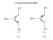
1. Circuit Symbols for BJTs. 2. 3. Example 5.1. 4. iC vBE Characteristic. 5. iC vCB Characteristics. 6. iC vCE Characteristics. 7 ...
| PowerPoint PPT presentation | free to download

BJTs amplifier requires a knowledge of both the DC analysis (large signal) and ... BJT need to be operate in active region used as amplifier. ...
| PowerPoint PPT presentation | free to view

... NPN Bipolar Junction Transistor Carrier Transport in a BJT BJT Band Diagram BJT Current Equations Forward-Active Region of a BJT Forward-Active Region of a ...
| PowerPoint PPT presentation | free to view

Title: No Slide Title Author: Paul Hasler Last modified by: ICE Lab Created Date: 5/12/2000 7:01:09 PM Document presentation format: On-screen Show
| PowerPoint PPT presentation | free to view

1. Small-Signal Operation of BJTs. 2. 3. 4. The Hybrid-p Model. 5. The T Model. 6. Example 5.14. 7. 8. Augmented Small-Signal Models ...
| PowerPoint PPT presentation | free to download

CB is derived from the fact that the : ... Set VCB at one value (fixed value of VCC) ... Two set of characteristics are necessary to describe the ...
| PowerPoint PPT presentation | free to view

Invented in 1948 at Bell Telephone Laboratories. Dominant ... the same way PMOSFET works ... The transistor performs as a voltage controlled current source ...
| PowerPoint PPT presentation | free to view
for BJTs Using a Single Power Supply. 3. Biasing the BJT Using Two Power Supplies. 4. Biasing Using a Collector-to-Base Feedback Resistor ...
| PowerPoint PPT presentation | free to download

Lecture #22 OUTLINE The Bipolar Junction Transistor Introduction Reading: Chapter 10 Bipolar Junction Transistors (BJTs) Introduction Charge Transport in a BJT ...
| PowerPoint PPT presentation | free to view

In order to conserve space, work at lower beta than small-signal BJTs. ... wide E/narrow contact Xmas tree. efficient use of space && better than xmas tree ...
| PowerPoint PPT presentation | free to view

Netlist Input: SPICE, Verilog, EDIF, LSIM, SPF, SPEF. Stimulus: .vec, Verilog HDL testbenches (VCS required) Models: BJTs, BSIM3.x, BSIM 4.x ...
| PowerPoint PPT presentation | free to view

The base current of the second BJT is the load current, divided by the second BJT's beta: ... and with a beta equal to the product of the individual betas. ...
| PowerPoint PPT presentation | free to view
JFETs Junction Field Effect Transistors Rick Matthews Department of Physics Wake Forest University Beyond Bipolar Bipolar transistors (NPN and PNP) require a base ...
| PowerPoint PPT presentation | free to download
... (rather than carriers injected into the emitter Professor Chenming Hu Semiconductor Devices ... We will follow the convention used in the textbook ICp ICn ...
| PowerPoint PPT presentation | free to download

Title: No Slide Title Author: iccuser Last modified by: Stig Munk-Nielsen Created Date: 9/30/2003 1:15:21 PM Document presentation format: On-screen Show
| PowerPoint PPT presentation | free to download

This article discuss about the Bipolar Transistor also called Bipolar Junction Transistors or BJT including the Types, working and applications
| PowerPoint PPT presentation | free to download
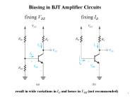
Section 5.5 Biasing of BJT Amplifier circuit Biasing of BJT Amplifier circuit Biasing to establish constant DC Collector current Ic & should be Calculatable ...
| PowerPoint PPT presentation | free to download

References for further information. Power Electronics by Mohan ... 34. Without Clamping. 35. The load resistance RC should satisfy the condition. IC IL ...
| PowerPoint PPT presentation | free to view

Biasing of BJT Amplifier circuit ... Two Power Supplies Version Figure 5.46 (a) A common-emitter transistor amplifier biased by a feedback resistor RB.
| PowerPoint PPT presentation | free to download

Contents. Cascade, cascode and Darlington connection. Feedback pair. CMOS circuit ... Zo = RC = 2.2k. Combination of FET and BJT Cascade ...
| PowerPoint PPT presentation | free to view

Collector. Ic, , mA. Forward active region. VCE. 70 A. Increasing Ib. NPN BJT. NPN BJT. B ... All devices are sized to fit the default grid. V1. I1. Q23. R23 ...
| PowerPoint PPT presentation | free to view

9 Applications of BJT
| PowerPoint PPT presentation | free to view

Bipolar Junction transistor Holes and electrons determine device characteristics Three terminal device Control of two terminal currents Amplification and switching ...
| PowerPoint PPT presentation | free to download

The reverse biased p-n junction results in zero drain current. ... Note that the BJT and MOSFET are both back-to-back p-n diodes, ...
| PowerPoint PPT presentation | free to download

Seventh International Symposium on Low Temperature Electronics. 14 October 2003, ... Larger-Area and Modified Doping (for Lateral Ge) Higher I and higher Vbk ...
| PowerPoint PPT presentation | free to view

Actual Motor Construction. Multi-pole Rotation, One-Coil On ... VR Stepper Motor 'One phase on' Stepping 'Two phase on' Stepping. Half-stepping. Unipolar motor ...
| PowerPoint PPT presentation | free to view

BJT circuit symbols. As shown, the currents are positive quantities when the ... 1 = hole current lost due to recombination in base, IBR ...
| PowerPoint PPT presentation | free to view

Describe the nature of both the base and collector characteristic curves for a BJT. ... 17. Base characteristic with collector-to-emitter voltage constant. ...
| PowerPoint PPT presentation | free to view

When we apply a large reverse bias (negative voltage) onto a diode, it ... anode. grid. electrons. vacuum. 1930. Remember the field effect transistor. ...
| PowerPoint PPT presentation | free to view

Actuators are the means for embedded systems to modify the physical world ... Close-up. Tang/Nguyen/Howe. Layout of electrostatic-combdrive. Ground plate. Folded beams ...
| PowerPoint PPT presentation | free to download

In active mode collector current is controlled by base current and base-emitter ... The device acts like an open circuit between collector and emitter: Circuit model: ...
| PowerPoint PPT presentation | free to view

Drivers. Air. Elevator. Conveyor. Robot. Car. Applications. Sensors. Controllers ' ... Uncontrolled Turn on and off (diode) Controlled turn on and Uncontrolled ...
| PowerPoint PPT presentation | free to view
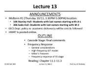
Lecture 13 ANNOUNCEMENTS Midterm #1 (Thursday 10/11, 3:30PM-5:00PM) location: 106 Stanley Hall: Students with last names starting with A-L 306 Soda Hall: Students ...
| PowerPoint PPT presentation | free to download

At the end of the lecture, student should be able to: ... Example of having a chopper circuit that requires switching to control output voltage ...
| PowerPoint PPT presentation | free to view

Serious VLSI research, design and cutting-edge manufacturing takes place in extremely sophisticated factories and labs (fabs). * Thank YOU!
| PowerPoint PPT presentation | free to view

Jaeger/Blalock. 10/21/03. Microelectronic Circuit Design. McGraw-Hill. Chap 9 - 1. Chapter 9 ... Richard C. Jaeger. Travis N. Blalock. Jaeger/Blalock. 10/21/03 ...
| PowerPoint PPT presentation | free to view

This article discusses about types of transistors and basic applications.Common types of transistor are BJT, FET, HBT, Darlington, Schottky, JFET, Diffusion
| PowerPoint PPT presentation | free to download

Jaeger/Blalock. 7/1/03. Microelectronic Circuit Design. McGraw-Hill. Chapter 16 ... Richard C. Jaeger. Travis N. Blalock. Chap 16 - 1. Jaeger/Blalock. 7/1/03 ...
| PowerPoint PPT presentation | free to view

ECE 8830 - Electric Drives Topic 1: Introduction to Electric Drives Spring 2004 Introduction Nearly 65% of the total electric energy produced in the USA is ...
| PowerPoint PPT presentation | free to view

The difference between NPN and PNP transistor mainly include what is a transistor, what are PNP and NPN transistors, Construction and working of transistors
| PowerPoint PPT presentation | free to download

Corrosion, electromigration, interdiffusion, ... Charge trapping. High electric field ... corrosion, electromigration, interactions, interdiffusion, restructuring, ...
| PowerPoint PPT presentation | free to view

... (high voltage direct-current HVDC); ... (revistas) dispon veis na Biblioteca Central da PUCRS; IEEE Transactions on Industrial Electronics; ...
| PowerPoint PPT presentation | free to view

TRANSITORES DE EFECTO DE CAMPO (Field effect transistor, FET) INTRODUCCI N: Son dispositivos de estado s lido Tienen tres o cuatro terminales Es el campo el ctrico ...
| PowerPoint PPT presentation | free to download

Characterize Ge devices at cryogenic temperatures ... Improve Device Characteristics (Reverse Breakdown Voltage, for example) Demonstrate Ge MOSFETs ...
| PowerPoint PPT presentation | free to view

The physics of
| PowerPoint PPT presentation | free to view
Chapter 7 Differential Amplifiers and Integrated Circuit (IC) Amplifiers Chapter 7 Differential Amplifiers and Integrated Circuit (IC) Amplifiers Figure 7.46 Small ...
| PowerPoint PPT presentation | free to download

... Box Electronics. An Introduction to Applied Electronics. in ... Next: 3. Digital Electronics. 4. Sample Circuits. 5. Simulations: Spice is your Friend ...
| PowerPoint PPT presentation | free to view

For the emitter-stabilized biase cct of Fig. 5.15, determine IBQ, ICQ, VCEQ, VC, VB, VE. ... VBE decreases 7.5mV every degree celcius. ICO doubles every 10 oC ...
| PowerPoint PPT presentation | free to view

The three terminals of a transistor are named as emitter E, collector C, ... than a few tenths of a volt above the emitter), useful for amplifier applications ...
| PowerPoint PPT presentation | free to view

Basics of Transistor operation. Transistor Types. Practical ... VAC(a) VDC. VAC(b) VAC(c) N. 3 Rectifier Waveforms. Delay angle. Uncontrolled (max) RMS voltage ...
| PowerPoint PPT presentation | free to view

Mixer Design Introduction to mixers Mixer metrics ... Unfortunately this results in increasing the noise figure of the mixer (as discussed in LNA design).
| PowerPoint PPT presentation | free to download

Faculty of Electrical and Electronics Engineering. Learning Outcomes ... Analyzed or design of a transistor amplifier that require a dc response of the system ...
| PowerPoint PPT presentation | free to view

Field Effect Transistors (FETs) In a field effect transistor, current flow through a semiconductor channel is controlled by the application of an electric field ...
| PowerPoint PPT presentation | free to view

... doped region and collector is most lightly doped region. ... Due to doping differences, base-emitter diode has relatively low breakdown voltage (3 to 10 V) ...
| PowerPoint PPT presentation | free to view

... transistor power dissipation using the ... Transistor power dissipation = VCEIC = 24 mW ... Iz and power dissipation in Q1. Vo= VZ VBE = 10-0.7 = 9.3V ...
| PowerPoint PPT presentation | free to view

Based on Underlying Semiconductor Technology. Transistor-Transistor Logic: TTL ... MOSFETs on input to provide high input impedance ...
| PowerPoint PPT presentation | free to view